


What Is the Difference Between 2-Wire, 3-Wire, and 4-Wire RTD
Resistance Temperature Detector ( RTD) sensors are widely used in industrial and laboratory temperature measurement because they offer high accuracy and long-term stability.
However, RTD accuracy does not depend only on the sensor itself. The wiring method—2-wire, 3-wire, or 4-wire—also plays a major role. Different wiring configurations handle lead resistance in different ways, and improper selection can introduce significant measurement errors.
In this article, we explain the three RTD wiring types and compare their accuracy, cost, and typical applications.
Understanding RTD Wiring Configurations
RTD wiring refers to how you connect the sensor to the measuring instrument. Each configuration uses a different number of wires and handles lead resistance differently, which directly affects measurement accuracy.
The three most common types are 2-wire, 3-wire, and 4-wire RTDs.
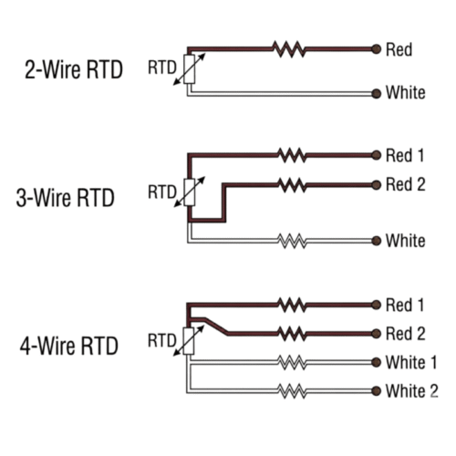
2-Wire RTD
A 2-wire RTD uses two conductors to connect directly to the sensing element. The instrument sends a current through the loop and calculates temperature based on total resistance.
This design keeps things simple. It reduces cable cost and installation time. It also works with almost all PLCs and temperature instruments without special input modules.
For short distances (usually under 10 meters) and low-accuracy applications, a 2-wire RTD can work well.
However, this setup cannot remove lead wire resistance. The system measures both the RTD resistance and the wire resistance together. Over long distances, this can create large errors. For example, a 100-meter cable can introduce up to 22°C of measurement error, depending on wire type and conditions.
Wire length, material, and temperature changes also affect the reading. Even small changes can cause signal drift over time. Because of this, 2-wire RTDs are only suitable for short-distance and non-critical applications.
3-Wire RTD
A 3-wire RTD is the most common industrial configuration. More than 80% of industrial process systems use this setup.
It uses three wires: two connect to one side of the RTD element, and one connects to the other side. The measuring system uses a bridge circuit to compensate for lead resistance.
This design offers a strong balance between cost and accuracy. It removes about 99% of lead resistance errors. At 100 meters of cable, the typical error stays within ±0.1°C to ±0.5°C.
It also supports cable lengths up to 500 meters, and most PLCtemperature modules support it directly. Because of this, industries such as HVAC, food processing, tanks, and pipelines widely adopt 3-wire RTDs.
However, 3-wire RTDs require matched wire resistance. If wires differ in length, material, or temperature, accuracy drops. Electrical noise can also affect the signal if you do not use shielded cables.
Even with these limits, the 3-wire RTD remains the best choice for most industrial applications.
4-Wire RTD
A 4-wire RTD delivers the highest accuracy.
It uses two wires to supply a constant current to the RTD element, and two separate wires to measure voltage directly across the sensor.
Because almost no current flows through the sensing wires, their resistance does not affect the measurement. This method is called a Kelvin connection.
The Kelvin method removes all lead wire resistance errors. The result does not depend on cable length, wire type, or temperature changes. This allows accuracy down to ±0.03°C, making it suitable for high-precision applications.
Industries such as pharmaceuticals, semiconductor manufacturing, laboratory calibration, and aerospace rely on 4-wire RTDs for critical measurements.
The main drawback is cost and complexity. It requires more wiring and compatible 4-wire instruments. However, in high-value processes, it helps avoid costly measurement errors and improves system reliability.
Comparison: 2-Wire vs 3-Wire vs 4-Wire RTD
The table below summarizes the key differences.
| Feature | 2-Wire RTD | 3-Wire RTD | 4-Wire RTD |
|---|---|---|---|
| Typical Accuracy | Poor (±5–22°C at 100m) | Good (±0.1–0.5°C at 100m) | Excellent (±0.03°C, not affected by distance) |
| Lead Wire Compensation | None | Partial (requires matched leads) | Full (Kelvin connection) |
| Maximum Practical Cable Length | <10 m ( beyond this, lead resistance adds directly, causing large errors (e.g., 22°C at 100m)) | ≤500 m (residual error typically <0.5°C within 500m; beyond 500m, matching difficulty increases and accuracy degrades) | ≤500 m ( typical in industrial environments. The limit is not due to lead resistance (theoretically unlimited) but because the weak signal (1mA excitation) picks up EMI. In low‑noise labs, >1000 m is possible. For very long runs, use a 4‑20 mA transmitter) |
| Cost | Lowest | Medium | Highest |
| Wiring Complexity | Simple | Moderate | Higher |
| Typical Applications | Low‑cost indicators, short‑distance non‑critical monitoring, prototyping | Industrial process control (tanks, pipes, reactors), HVAC (industrial & commercial buildings), food & beverage, clean rooms | Laboratories, calibration equipment, pharmaceuticals, precision research |
How to Choose the Right RTD Wiring
Selecting the correct RTD wiring method requires considering measurement distance, accuracy requirements, device compatibility, budget, and environmental conditions.
1. Measurement Distance
Short distances (<10–20 m) can use 2-wire RTDs. Medium distances (tens to hundreds of meters) are best suited for 3-wire RTDs. For long distances, installing a temperature transmitter near the sensor is recommended to convert the signal to a 4–20 mA current loop or digital fieldbus (HART/Modbus) for improved reliability.
2. Accuracy Requirements
- ±2°C tolerance → 2-wire RTD
- ±0.5–1°C industrial standard → 3-wire RTD
- ±0.1°C high precision → 4-wire RTD
3. Device Compatibility
Always verify PLC or transmitter input support. Most devices support 3-wire RTDs, while 4-wire inputs require dedicated channels and may increase system cost.
4. Budget Consideration
2-wire < 3-wire < 4-wire. In most cases, 3-wire RTD offers the best cost-performance ratio.
Environmental Considerations
- Strong EMI environments (motors, VFDs): use shielded twisted-pair cables
- 3-wire systems require strictly matched wire resistance
- Large temperature gradients: 4-wire RTD is preferred for maximum stability
Conclusion
RTD measurement accuracy depends not only on the sensor itself but also heavily on the wiring configuration. The 2-wire RTD is simple and low-cost but introduces significant errors due to lead resistance. The 3-wire RTD provides an excellent balance between accuracy and cost, making it the most widely used solution in industrial applications. The 4-wire RTD delivers the highest accuracy by completely eliminating lead resistance through Kelvin measurement, making it ideal for laboratories and high-precision manufacturing.
In real-world applications, there is no single “best” wiring method—only the most suitable one. The correct choice depends on distance, accuracy requirements, system compatibility, and environmental conditions. In some cases, using a temperature transmitter can further optimize system performance.
Selecting the right RTD wiring method not only reduces measurement errors but also significantly improves system stability and long-term reliability—making it a critical design decision in temperature measurement systems.