


What Is Cold Junction Compensation in Thermocouple
In industrial temperature measurement, thermocouples remain one of the most widely used temperature sensors because they offer a wide range, rugged construction, and a relatively low cost. However, to get relatively accurate readings, you must understand one of their core characteristics: cold junction compensation (CJC).
This article explains what thermocouple cold junction compensation is, why you need it for thermocouple temperature measurement, how it is implemented, and what key factors you should pay attention to when you apply it in real systems.
1. Introduction to Thermocouples
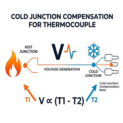
A thermocoupleconsists of two different metal wires joined at one end, called the hot junction, while the other end connects to a measuring instrument or terminal block, known as the cold or reference junction. When the hot junction and the cold junction sit at different temperatures, theSeebeck effectgenerates a small voltage between the two points. This voltage is proportional to the temperature difference between the two junctions, not the absolute temperature of the hot junction.
In other words, the raw voltage from a thermocouple tells you the difference between the hot end and the cold end, but not the hot‑end temperature by itself. You must also know the cold‑end temperature to recover the true hot‑junction temperature.
In laboratory calibration setups, engineers often hold the cold junction at 0 °C using an ice bath. In most industrial environments, however, the cold junction sits at room temperature—typically 20 °C to 30 °C—and fluctuates with the environment. If you ignore this changing cold‑junction temperature, your measurement will show a systematic offset, and your reported values will not match the real temperature at the hot junction.
2. What Is Cold Junction Compensation in Thermocouple
Cold junction compensation (CJC) solves exactly this problem. CJC corrects the thermocouple output voltage so that the final reading reflects the true temperature at the hot junction, even when the reference junction is not at 0 °C. In plain terms, CJC translates the measured voltage into a temperature value referenced to the actual temperature at the instrument’s terminals, rather than assuming a fixed 0 °C reference.
The term “cold junction” is partly historical: the junction is not always cold, but simply the reference point where the thermocouple wires connect to copper traces or the measurement system. For this reason, many engineers also use “reference junction compensation” as a synonym for cold junction compensation.
Modern instruments typically handle CJC automatically in the measurement hardware or software, but the underlying idea stays the same: you measure the reference‑junction temperature, convert it into an equivalent thermocouple voltage, and then use that value to correct the measured thermocouple signal. By doing this, you eliminate the error introduced by a changing cold‑junction temperature and recover the true hot‑junction temperature.
3. Why Cold Junction Compensation Is Required in Thermocouples
International standardsNISTand ITS‑90define the thermocouple voltage-temperature relationship assuming the reference junction sits at 0°C. Because the thermocouple curve is non-linear, a simple linear subtraction of the ambient temperature is often insufficient for high-precision applications.
For example, with a K-type thermocouple, if the cold junction is at 30°C and the system assumes 0°C, the reported temperature could be off by approximately 30°C. In industries like semiconductor manufacturing or heat treating, such a bias can lead to product defects, safety hazards, and decreased energy efficiency. For any system where accuracy matters, CJC is a basic requirement.
4. How Cold Junction Compensation Is Done in Thermocouples
4.1 Core Principle
The core idea behind cold junction compensation breaks down into a few clear steps:
- Measure the thermocouple output voltage
VTC. - Measure or estimate the cold junction temperature
TCJ. - Use the standard table or polynomial for your thermocouple type to convert
TCJinto an equivalent thermocouple voltageVCJC. - Calculate the corrected voltage
Vcorrected = VTC + VCJC. - Use the same reference tables or polynomials to convert
Vcorrectedback into temperatureThot.
The resulting Thot is the true hot‑junction temperature, referenced to the actual temperature at the measurement terminals.
4.2 Main Implementation Methods
Ice‑point reference (ice bath)
The most conceptually straightforward and accurate method is to hold the reference junction at 0 °C using an ice‑water bath. In this setup, TCJ = 0 °C and VCJC = 0, so you can directly use standard tables to convert the measured VTC into temperature.
However, this method is not practical for most industrial applications. Ice‑water baths take up space, require maintenance, and are poorly suited for field‑mounted instruments. Engineers mainly reserve them for calibration laboratories and metrology setups.
Fixed Reference Temperature
In some systems, the reference junction is maintained at a known but non-zero temperature using a controlled thermal environment, such as an isothermal block. The system then compensates based on this known reference temperature rather than assuming 0 °C.
This approach can reduce measurement error compared to an uncontrolled ambient condition. However, it still requires a stable and uniform thermal environment, which is difficult to guarantee in most industrial installations. As a result, it is less commonly used in modern field applications and is typically limited to specialized or semi-controlled environments.
Analog Cold Junction Compensation
In analog implementations, designers place a temperature‑sensitive element—such as anRTD, thermistor, or semiconductor sensor—near the terminal block. They then combine the sensor’s output with the thermocouple signal using analog circuitry, such as a voltage‑summing network or op‑amp circuit, so that the total output voltage corresponds to the correct hot‑junction temperature.
Analog CJC is simple and inexpensive but less flexible. It responds strongly to component tolerances, temperature drift, and PCB layout, so engineers use it less often in modern high‑precision systems.
Digital cold junction compensation
In modern instruments, engineers usually implement cold junction compensation digitally:
- An analog‑to‑digital converter (ADC)reads the thermocouple voltage
VTC. - A separate sensor (often an integrated IC) near the terminal block measures the cold junction temperature
TCJ. - Software running on a microcontroller, PLC, or data acquisition system performs the following steps:
- converts
TCJinto an equivalent thermocouple voltageVCJC - adds it to
VTC - uses standard tables or polynomials to convert
VcorrectedintoThot.
- converts
This approach is flexible, repeatable, and easy to calibrate, and it appears widely in temperature controllers, data loggers, and industrial data acquisition (DAQ)systems.
4.3 Using the correct compensation curve for the thermocouple type
The principle of cold junction compensation stays the same for all thermocouple types—K, J, T, N, and others—but the voltage‑temperature curves and polynomial coefficients differ. For example, a K‑type thermocouple CJC algorithm must use K‑type reference tables or polynomials, not those for J‑type.
Many integrated thermocouple amplifiers and ICs let you select the thermocouple type, and the device then automatically applies the correct CJC curve and polynomial. This choice greatly simplifies design and reduces the risk of mismatches between sensor type and compensation method.
5. Practical Considerations for Implementing Cold Junction Compensation
5.1 Sensor Placement and Thermal Uniformity
The accuracy of cold junction compensation strongly depends on where and how you measure the cold junction temperature. You should place the sensor as close as possible to the thermocouple terminals or connector, ideally on the same PCB or in the same local environment. If the sensor sits far from the junctions or in a different thermal zone, the measured TCJ may not reflect the true cold‑junction temperature, and the compensation will be inaccurate.
You should also keep the area around the terminals at a relatively stable and uniform temperature. Avoid placing the cold junction near heat sources such as power supplies, heaters, or high‑current traces, because these components create local temperature gradients and offset errors.
5.2 Choosing the Right Type of Compensation for Your Application
In calibration or laboratory environments, where high accuracy is critical and you can physically maintain 0 °C, an ice‑point reference remains a valid option. In most industrial field applications, however, engineers strongly prefer digital cold junction compensation or integrated thermocouple amplifiers with built‑in CJC. These devices combine amplification, ADC, and temperature sensing in a single package, reducing design complexity and improving system reliability.
Using a thermocouple amplifier with cold junction compensation also simplifies noise filtering, offset trimming, and calibration, which is especially valuable in industrial environments with electromagnetic interference and long‑distance signal runs.
5.3 Accuracy, Calibration, and Reference Data
Keep in mind that cold junction compensation only corrects the error from the reference junction. Your overall system accuracy depends on several factors:
- the accuracy and calibration of the thermocouple itself
- the accuracy of the cold junction temperature sensor (for example, ±0.1 °C versus ±1 °C)
- the resolution and linearity of the ADC
- the quality of the reference tables or polynomials you use in the conversion
To achieve high‑precision measurement, you should use well‑established tables—for example, from NIST or recognized standards bodies—and validate your system at known temperature points, such as the ice point, boiling‑point, or a calibrated dry‑block oven. In production systems, periodic calibration against a reference standard helps maintain long‑term accuracy.
5.4 Connection, Wiring, and Noise
Proper wiring and grounding practices are essential for reliable thermocouple measurements. When you need to extend the signal, use thermocouple‑grade extension wires or compensating wires that match your thermocouple type, and avoid mixing different thermocouple types, because their Seebeck characteristics differ. Long, unshielded wires can introduce offset voltages and noise, and cold junction compensation cannot correct these interference effects.
Shielded cables and proper grounding reduce electromagnetic interference and ground‑loop effects that can distort the small thermocouple signal. In high‑noise environments, you can further improve signal integrity by using differential inputs, low‑pass filtering, and isolation techniques.
5.5 Environmental and Operational Factors
In harsh environments—high temperature, high vibration, or corrosive atmospheres—the mechanical integrity of connectors and terminals becomes critical. A loose or damaged connection introduces contact resistance and local temperature gradients, which degrade the effectiveness of cold junction compensation.
In continuous process control applications, even small biases in temperature measurement can accumulate into significant errors over time. By implementing robust cold junction compensation and appropriate signal conditioning, you can keep your thermocouple‑based measurements accurate and reliable across the entire operating range.ime. By implementing robust cold junction compensation and appropriate signal conditioning, you can keep your thermocouple‑based measurements accurate and reliable across the entire operating range.
6. Summary
Cold junction compensation is the basic prerequisite for accurate thermocouple measurement, because a thermocouple outputs a differential temperature signal and the cold‑end temperature must be corrected. Modern systems usually adopt digital compensation or integrated amplifiers to automatically complete the temperature‑to‑voltage conversion and summation.
By understanding the compensation principle and following good design practices—reasonable layout, proper wiring, and accurate reference data—you can ensure that the measurement results are accurate and repeatable.
When selecting or designing a thermocouple system, always pay attention to how the device implements cold junction compensation and whether it offers integrated support; this choice directly affects your system’s complexity, accuracy, and long‑term reliability.