


Semi-Rigid Cable Assemblies
Semi-Rigid Cable Assemblies
Key Features
- Solid, seamless outer conductor for exceptionally low insertion loss
- Shielding effectiveness exceeding 130 dB with virtually no signal leakage or crosstalk
- Excellent phase stability for phase-matched systems, radar, and RF test applications
- Forms into precise, permanent shapes for fixed installations
- Standard diameters from 0.020″ to 0.250″, including 0.037″ and 0.085″
- Copper or aluminum outer conductor with copper, silver-plated copper, or copper-clad steel center conductor options
- PTFE dielectric supports operating temperatures from -55°C to +200°C
- Frequency coverage up to 65 GHz as standard and up to 110 GHz with 1.0 mm connectors
- Compatible with SMA, N-Type, and precision millimeter-wave connectors
- Available as direct replacements for legacy RG-402 and RG-405 cable assemblies
- MIL-DTL-17 compliant construction available with full electrical test data and material traceability
- sales@connector-sensor.com
- +86 15120067961
- Cable Assemblies9 products
- Connectors124 products
- Sensors121 products
- Automotive Sensors11 products
- Position Sensors1 product
- Proximity Sensors1 product
- Flow Sensors9 products
- Force Sensors21 products
- Gas Sensors18 products
- Photoelectric Sensors14 products
- Pressure Sensors19 products
- Temperature and Humidity Sensors3 products
- Temperature Sensors24 products
- Vision Sensors10 products
- IMU Sensor1 product
- Optoelectronic Modules1 product
Semi-Rigid Cable Assemblies
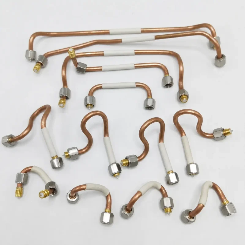
Semi-rigid cable assemblies provide exceptionally low insertion loss, excellent phase stability, and outstanding shielding effectiveness. These advantages make them the preferred choice for RF and microwave systems where signal integrity is critical. Unlike braided coaxial cables, semi-rigid coax uses a solid, seamless metal outer conductor that retains its shape after forming, helping maintain consistent transmission-line performance throughout the product’s service life.
We manufacture semi-rigid cable assemblies in diameters from 0.020″ to 0.250“, including the widely used 0.037″ and 0.085″ sizes. Assemblies are available with copper or aluminum outer conductors and can be terminated with SMA, N-Type, and other standard or precision RF connectors. Every assembly is supplied with complete electrical test data.
What Is Semi-Rigid Cable Assembly?
A semi-rigid cable assembly is a coaxial transmission line consisting of a solid center conductor, a PTFE dielectric, and a seamless drawn-metal outer-conductor tube, typically made from copper, tin-plated copper, or aluminum. Unlike braided coaxial cable, the continuous metal outer conductor completely encloses the dielectric, providing excellent shielding performance and a highly consistent cable geometry over the entire length.
Because the outer conductor is a solid tube, semi-rigid cable can be formed with specialized tooling into precise, permanent shapes that fit the available space inside equipment. Once formed, it maintains its shape under normal operating conditions. This combination of stable electrical performance and dimensional consistency makes semi-rigid cable well suited for applications where cable routing remains fixed throughout the product’s service life.
Why Choose Our Semi-Rigid RF Cable Assemblies?
- Lowest Insertion Loss
The solid center conductor and seamless outer conductor minimize conductor and radiation losses while maintaining low VSWR and stable attenuation across the operating frequency range. Compared with flexible and hand-formable coaxial cables of the same size, semi-rigid cable typically delivers lower transmission loss.
- Excellent Shielding Effectiveness
The continuous, seamless metal outer conductor eliminates the gaps found in braided constructions, providing shielding effectiveness exceeding 130 dB with virtually no signal leakage or crosstalk. This makes semi-rigid cable well suited for high-density RF systems, test equipment, and avionics applications.
- Outstanding Phase Stability
The fixed cable geometry and solid outer conductor reduce the effects of temperature variation and mechanical movement on electrical performance. As a result, semi-rigid cable is widely used for phase-matched cable assemblies in radar, phased-array, and precision RF test systems.
- Precise and Repeatable Performance
The rigid outer conductor helps maintain consistent electrical length and characteristic impedance from installation through long-term operation. This repeatability is especially important in applications where calibration accuracy must be maintained over time.
- Broad Frequency Coverage
Standard semi-rigid cable assemblies support frequencies up to 65 GHz. Assemblies terminated with 1.0 mm connectors can operate at frequencies up to 110 GHz, making them suitable for high-frequency and millimeter-wave test applications.
Key Specifications
| Specification | Details |
|---|---|
| Sizes | Outer diameters from 0.020″ to 0.250″, covering common UT and RG series (including 0.037″, 0.047″, 0.085″ (RG-405), 0.141″ (RG-402), and 0.250″). |
| Impedance | Standard 50 Ω for most RF and microwave applications. Other impedance options are available for specialized matching requirements. |
| Insertion Loss | Typically 0.1–0.5 dB/m from 1–10 GHz, depending on cable size and construction. |
| Higher-Order Mode Limit | Each cable size has a cutoff frequency above which higher-order propagation modes may occur. Typical limits are 35–40 GHz for 0.141″, 65 GHz for 0.085″, and over 100 GHz for 0.047″ cables. |
| Dielectric Withstanding Voltage | Typically 500–2000 V, depending on cable size and dielectric construction. |
| Operating Temperature | -55°C to +200°C with PTFE dielectric, suitable for demanding industrial, aerospace, and defense environments. |
| Shielding Effectiveness | Exceeds 130 dB with a seamless metal outer conductor, providing excellent protection against signal leakage and crosstalk. |
Construction & Materials
Center Conductor – Available in solid bare copper, silver-plated copper, or copper-clad steel to balance conductivity, mechanical strength, and cost.
Dielectric – Solid PTFE (Teflon) provides low dielectric loss, a stable dielectric constant, and reliable performance across a wide temperature range.
Outer Conductor – Copper, tin-plated copper, or aluminum options offer different advantages in conductivity, solderability, and weight reduction.
Plating – Tin or tin-lead plating improves solderability while increasing corrosion resistance.
Jacket – Bare construction is standard for easy forming. Optional FEP or heat-shrink jackets provide additional abrasion and environmental protection.
Applications of Semi-Rigid Cable Assemblies
- Test & Measurement – Precision VNA test cables and laboratory reference assemblies requiring calibration-grade performance.
- Radar & Phased-Array Systems – Phase-matched cable assemblies that maintain accurate channel-to-channel phase tracking.
- Aerospace & Defense – Avionics, missile guidance, and other mission-critical RF and microwave systems.
- Telecommunications Infrastructure – Fixed RF interconnects for base stations, radio units, and network equipment.
- Satellite & Space Systems – Lightweight, permanently formed interconnects designed to withstand launch vibration and long-term operation.
- Precision Instrumentation – Internal RF signal paths where dimensional stability directly affects measurement accuracy.
Quality & Testing
Every semi-rigid cable assembly undergoes comprehensive electrical testing before shipment. We verify insertion loss, VSWR (or return loss), shielding effectiveness, and electrical continuity across the specified operating frequency range. This ensures every assembly performs as tested—not simply to the nominal specifications listed in the datasheet.
Phase-matched cable assemblies are manufactured and tested as complete sets in a controlled environment to verify channel-to-channel phase tracking. When required, we also provide MIL-DTL-17-compliant construction, material traceability, and formal electrical test reports.
How to Choose the Right Semi-Rigid Cable Assembly
1. Determine the operating frequency.
Higher frequencies generally require smaller cable diameters to maintain the desired transmission performance.
2. Consider insertion loss and power handling.
Larger cable sizes typically offer lower attenuation and higher power capacity, while smaller sizes are better suited to compact installations.
3. Confirm the installation environment.
Semi-rigid cable is best suited for applications where the routing remains fixed after installation.
4. Select the conductor material.
Choose copper for maximum conductivity and easy soldering, or aluminum when reducing weight is a priority.
5. Identify any special requirements.
If your project requires phase-matched assemblies, MIL-DTL-17 compliance, or material traceability, specify these requirements before production.
6. Choose the connector interface.
Confirm the connector series, gender, and cable size to ensure compatibility with your existing equipment.
Why Source Semi-Rigid Cable Assemblies From HUADA
HUADA manufactures semi-rigid cable assemblies to customer drawings or performance specifications across standard UT- and RG-equivalent cable sizes, including 0.037″, 0.085″, 0.141″, and other common configurations. Copper and aluminum outer-conductor options are available, together with standard and precision RF connector interfaces.
Every assembly is precision formed and electrically tested before shipment. Insertion loss, VSWR (or return loss), shielding effectiveness, and electrical continuity are verified, with complete electrical test data available upon request. We support both prototype development and volume production, including phase-matched cable sets, custom cable lengths, and cross-reference replacements for existing part numbers.
Frequently Asked Questions
1. What makes semi-rigid cable different from other RF coaxial cables?
Semi-rigid cable uses a seamless metal tube instead of a braided outer conductor. This construction provides lower insertion loss, higher shielding effectiveness, and better phase stability, while allowing the cable to retain a permanent shape after forming.
2. Can a semi-rigid cable assembly be reshaped after installation?
Reforming is not recommended. Repeated bending can damage the outer conductor, reducing shielding performance and affecting impedance consistency. If routing changes are expected, semi-flexible or flexible coaxial cable is generally a better choice.
3. What frequency range do semi-rigid cable assemblies support?
Standard semi-rigid cable assemblies support frequencies up to approximately 65 GHz. Assemblies fitted with 1.0 mm precision connectors can operate at frequencies up to 110 GHz for millimeter-wave applications.
4. What is the difference between 0.037″ and 0.085″ semi-rigid cable?
The 0.037″ cable is designed for compact, high-frequency applications with limited installation space. The 0.085″ cable offers a balance of low insertion loss, power handling, and ease of installation, making it one of the most commonly used sizes.
5. Are SMA connectors available for semi-rigid cable assemblies?
Yes. SMA connectors are widely used on semi-rigid cable assemblies, particularly for 0.085″ and 0.141″ cables. We also offer precision 2.92 mm, 2.40 mm, 1.85 mm, and 1.00 mm connector options for higher-frequency applications.
6. Should I choose a copper or aluminum outer conductor?
Copper provides the highest conductivity and excellent solderability. Aluminum offers significant weight savings while maintaining good electrical performance, making it well suited to aerospace and weight-sensitive applications.
7. What center-conductor materials are available?
We offer solid bare copper, silver-plated copper, and copper-clad steel center conductors. Material selection depends on the required balance between electrical performance, mechanical strength, and cost.
8. Can you manufacture custom semi-rigid cable assemblies?
Yes. We manufacture assemblies to your required cable length, connector configuration, and routing drawing. Phase-matched cable sets and custom-engineered solutions are also available.
Ready to spec a semi-rigid cable assembly for your project?
Contact our engineering team with your frequency, size, and connector requirements for a configuration and quote.
Send Message to get Datasheet.
Strict Production Process
Engineers develop optimized electronic circuits and structural designs based on real application needs.
High-quality components and materials are carefully selected from trusted suppliers to ensure long-term reliability.
Automated SMT and precision soldering technologies are used to build stable and high-performance circuit boards.
Sensor elements or connector terminals are assembled with the PCB and housing to ensure accurate operation and strong mechanical stability.
Each product undergoes strict calibration and functional testing to guarantee accuracy and stable performance.
Every unit is carefully inspected, labeled, and securely packaged to ensure it arrives safely and performs reliably for your applications.
Strict Production Process of Yafeite