




D38999 Connector Guide: Types, Series, Applications & Part Numbers

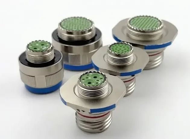
MIL-DTL-38999 connectors rank among the most widely deployed rugged MIL-Spec circular connectors in aerospace, defense, and other harsh-environment systems. Because they handle extreme vibration, high shock, moisture, and critical EMI shielded connector demands, the D38999 connector family serves as the default, trusted interconnect platform for hardware engineers globally.
When your project requires compact size, high contact density, and zero-failure mission-critical performance, this comprehensive D38999 circular connector guide will help you navigate the 4 core series, decode complex part numbers, and avoid costly sourcing mistakes.
1.What are D38999 Connectors
D38999 connectors represent subminiature, high-performance circular electrical connectors that compliy with the official United States military specification MIL-DTL-38999. Interestingly, China’s GJB 599A standard closely mirrors this identical design. Hardware designers specify this elite military connector because standard industrial-grade interfaces fail under severe environmental stress.
In the procurement and design phase, engineers rely on these defense connectors to deliver several critical advantages:
- Secure Mechanical Mating: The coupling mechanism prevents accidental decoupling under high-gravitational forces.
- Strong Resistance to Vibration: The rugged shell design withstands severe resonance found in missile launches and aero-engines.
- Reliable Signal and Power Transmission: Gold-plated contacts ensure low electrical resistance across thousands of mating cycles.
- Environmental Sealing: Advanced internal fluorosilicone seals achieve IP67/IP68 ratings to block moisture, sand, and aviation fuels.
- Compact, High-Density Layouts: The layout maximizes pin-count within minimal panel real estate.
- EMI/RFI Shielding: Shell-to-shell grounding fingers protect sensitive data from electronic warfare jamming and cross-talk.
Consequently, D38999 circular connectors function as the reliable hardware backbone for modern tactical infrastructure.
2. Why D38999 Connectors Matter
In high-reliability systems, the connector is never a secondary component. Instead, it represents a critical point of failure. Selecting an improper interface or material finish introduces severe engineering risks. For instance, an incorrect selection can cause galvanic corrosion on the launchpad or catastrophic signal attenuation at Mach 2.
Fortunately, MIL-DTL-38999 connectors solve several complex hardware challenges simultaneously:
- SWaP Optimization (Space, Weight, and Power): They allow smaller enclosures to pack high-density signals without sacrificing voltage ratings.
- Cross-Brand Intermateability: Because the official QPL (Qualified Products List) standard regulates this family, any standard D38999 plug seamlessly mates with an equivalent receptacle from another certified manufacturer. Therefore, you completely eliminate vendor lock-in.
- Modular Versatility: A single shell size accommodates standard copper wire, high-frequency RF coax, gigabit Ethernet data, or weight-saving fiber optics.
For these reasons, starting your design architecture with the D38999 standard drastically reduces testing cycles and speeds up your time-to-market for any aerospace connector or aviation connector application.
3. D38999 Series Overview: Understanding the 4 Core Series
The MIL-DTL-38999 specification divides the interconnect family into four distinct sub-families (Series I, II, III, and IV). Although they look similar externally, they feature completely incompatible coupling mechanisms, shell dimensions, and weight profiles.
| Series | Coupling Style | Key Mechanical Characteristic | Primary Disadvantage | Industry-Standard Shell Size Format |
|---|---|---|---|---|
| Series I | Bayonet | Fast 120° turn mating; 100% Scoop-Proof | Lower vibration rating than Series III | Numerical (9 to 25) |
| Series II | Low-Profile Bayonet | Ultra-lightweight; space-saving installation depth | Not Scoop-Proof; low vibration ceiling | Numerical (8 to 24) |
| Series III | Tri-Start Threaded | Self-locking connector mechanism; highest ruggedness; 100% Scoop-Proof | Slightly heavier; slower mating than bayonet | Alphabetical (A to J) |
| Series IV | Breech-Lock | 90° quick engagement; blind-mate friendly; excellent localized shock resistance | Highly complex construction; higher cost | Alphabetical (B to J) |
-Series I
Series I connectors utilize a standard 3-pin bayonet coupling mechanism. They perform exceptionally well in weight-conscious aerospace applications where technicians require rapid connection and disconnection during line-replaceable unit (LRU) swaps. Furthermore, the extended shell maintains full scoop-proof pin protection.
-Series II
Series II offers a lower-profile variant of the bayonet family. By shortening the shell length, this series achieves significant weight savings. However, engineers must note that Series II does not feature a scoop-proof design. As a result, technicians can easily bend long pins if they force the plug in at an angle during blind mating. Therefore, you should restrict its use to protected internal box-to-box wiring.
-Series III (The Global Benchmark)
Series III connectors represent the most widely deployed and specified members of the family. Utilizing a coarse, tri-start threaded coupling system with an integrated inner ratchet, this design functions as a premium self-locking connector. When tightened, it provides continuous metal-to-shell grounding and unmatched resistance to severe thermal and mechanical shock.
-Series IV
Series IV connectors employ a robust breech-lock style mechanism. With a minimal 90° rotation, the breech system locks the mated pair immediately. Consequently, factories heavily utilize Series IV in missile launching tracks, land-combat vehicles, and weapon umbilical lines where severe linear forces exist.
D38999 Series I vs Series III: What is the Difference?
The primary difference between D38999 Series I and Series III lies in the coupling mechanism and vibration tolerance. Specifically, Series I uses a 120° turn bayonet mechanism for rapid field deployment. In contrast, Series III uses a triple-start threaded, self-locking mechanism. Thus, Series III provides superior anti-decoupling performance under extreme vibration and remains the preferred standard for modern aerospace systems. Additionally, Series I uses numerical shell sizes (9-25), while Series III uses alphabetical shell size codes (A-J)
4. Common D38999 Connector Types & Shell Styles
Selecting the correct shell style dictates how your interconnect will interface with the structural enclosure or the external cable harness.
- Wall Mount Receptacle (D38999/20 for Series III): This style features a square flange with four mounting holes. Engineers install it on the exterior panel of a box, which allows a plug to connect from the outside.
- Jam Nut Receptacle (D38999/24 for Series III): This single-hole mounting style fixes to the panel via a rear hexagonal nut. It offers superior hermetic connector sealing performance and works excellently for space-limited panels, though it requires precise O-ring alignment.
- Box Mount Receptacle (D38999/21 for Series III): This type looks similar to the wall mount but lacks backshell threads. Therefore, factories use it strictly for terminating internal PCB traces or wire bundles inside an enclosure.
- Straight Plug Connector (D38999/26 for Series III): This standard cable-side component houses the coupling nut. It mates directly to the wall mount or jam nut receptacles.
- Right Angle Plug: Designers choose this variant primarily when routing cables in extremely tight enclosures where the minimum bend radius of the wire jacket prevents a straight exit.
5. D38999 Shell Size Chart & Insert Arrangements
To ensure complete compatibility, you must evaluate both the external shell dimensions and the internal contact grid.
In D38999 Series III, alphabetical letters A through J designate the shell sizes, which map directly to standard imperial dimensions:
| Series III Letter Code | Equivalent Numerical Size | Max Contact Capacity (High Density Layouts) |
|---|---|---|
| A | 9 | 9 |
| B | 11 | 13 |
| C | 13 | 22 |
| D | 15 | 37 |
| E | 17 | 55 |
| F | 19 | 66 |
| G | 21 | 79 |
| H | 23 | 100 |
| J | 25 | 128 |
Why Insert Arrangement Matters
The insert arrangement determines the physical placement, spacing, and gauge of the internal pins. For instance, Layout 19-35 (Shell Size F) dictates 66 ultra-fine 22D contacts, creating a dedicated high-density connector optimized for digital signals. Conversely, Layout 25-4 provides a lower count of heavy-duty Size 4 and Size 12 contacts, which optimize heavy power delivery.
Please note that mixing high-speed data protocols (like Ethernet or Mil-Std-1553) inside a poorly shielded insert layout can introduce severe electromagnetic cross-talk.
Technical Specs: Contact Types & Materials
Modern D38999 connectors support a hybrid architecture of electrical and optical termination mediums:
- Signal Contacts: Typically, these include Size 22D, 20, or 16 removable crimp contacts that handle low-amperage data and logic signals.
- Power Contacts: These heavy-duty Size 8 or Size 4 pins supply power directly to heavy power distribution systems.
- Coax & Twinax Contacts: These shielded contacts maintain concentric geometry. For this reason, they are ideal for RF microwave feeds and aircraft data bus lines.
- Quadrax Contacts: These components feature four outer pins in a shielded cell. Consequently, they allow high-bandwidth 100Base-TX Gigabit Ethernet transmission over ruggedized military cabling.
- Fiber Optic Contacts: These options incorporate ceramic ferrules inside standard D38999 cavities to enable lightweight, zero-EMI optical link transmission in radar systems.
Most standard military assemblies leverage rear-release crimp contacts. Because technicians insert and extract them via specialized plastic tools, they can perform rapid field repairs without soldering irons.
6. D38999 Connector Part Number Breakdown
The MIL-SPEC part number acts as a highly structured engineering code. If you miss-specify a single digit, you can compromise an entire system’s environmental seal or keying configuration.
Let us decode a common, high-reliability aerospace part number step-by-step:
D38999 / 20 W F 35 P N
│ │ │ │ │ │ └── 7. Alternate Keying Position (Normal)
│ │ │ │ │ └───── 6. Contact Type (Pin)
│ │ │ │ └──────── 5. Insert Arrangement (66 Contacts, Size 22D)
│ │ │ └──────────── 4. Shell Size Code (Letter F = Size 19)
│ │ └─────────────── 3. Service Class / Finish (Olive Drab Cadmium)
│ └────────────────── 2. Shell Style (Wall Mount Receptacle)
└────────────────────────── 1. Military Specification Prefix
-Military Specification Prefix (D38999/)
This prefix indicates full compliance with the official United States Department of Defense interconnect framework.
-Shell Style (20)
This digit defines the mounting configuration. Under Series III, the standard codes mean:
- 20 = Wall Mount Receptacle
- 24 = Jam Nut Receptacle
- 26 = Straight Cable Plug
-Service Class / Material & Plating Finish (W)
This character dictates environmental, chemical, and electrical survivability:
- W (Olive Drab Cadmium over Electroless Nickel): This option uses an aluminum base. It represents the military gold standard for high corrosion resistance (500-hour salt spray) and excellent electrical conductivity, though it is not RoHS compliant.
- F (Electroless Nickel): This finish uses an aluminum base. It provides excellent conductivity for superior EMI shielding and complies with RoHS standards, but it only tolerates 48 hours of salt spray.
- Z (Black Zinc Nickel): This choice uses an aluminum base. It represents the modern RoHS-compliant alternative to Cadmium. It offers 500 hours of salt spray resistance while maintaining excellent conductive grounding.
- K (Passivated Stainless Steel): This premium material handles temperatures up to +200°C and resists harsh marine environments, but it carries a heavy weight penalty.
-Shell Size Code (F)
Under Series III, the standard uses alphabetical identifiers. In this example, F corresponds to Shell Size 19.
-Insert Arrangement (35)
This number maps out the specific pin density layout. For example, looking up arrangement 35 under Shell Size 19 reveals 66 high-density Size 22D contacts.
-Contact Type (P)
This letter defines the electrical polarity of the contacts that ship with the connector shell:
- P = Pin (Male contacts)
- S = Socket (Female contacts)
- A = Connector supplied without pins
- B = Connector supplied without sockets
-Alternate Keying / Polarization (N)
This setting prevents cross-mating when multiple identical connectors sit side-by-side on the same control panel. Specifically, N stands for Normal (Standard) orientation, while letters A, B, C, D, and E rotate the internal master keys to physically block the wrong cable plug.
7. Materials, Finishes, and Environmental Performance
The choice of shell material and finish directly dictates the structural longevity of your interconnect system. For instance, selecting an improper finish can lead to structural failure via galvanic reaction or cause a total loss of EMI shielding due to surface oxidation.
- Aluminum Composite Shells (Service Class M/J): These materials offer up to a 40% weight reduction compared to pure aluminum. Therefore, they are ideal for satellite subsystems and weight-critical UAV airframes. Additionally, they extend mating durability to 1500 cycles.
- Marine Bronze Shells: Shipbuilders utilize these specialized variants in deep-sea naval electronics and submarine hull penetrations. They prevent rust formation entirely, even when permanently submerged in salt water.
D38999 vs MIL-DTL-26482: Head-to-Head Comparison
Engineers frequently debate whether to specify the MIL-DTL-38999 standard or fallback to the older MIL-DTL-26482 standard for rugged system designs.
- Density Profile: D38999 represents a subminiature family that optimizes high pin counts (up to 128 pins). On the other hand, MIL-DTL-26482 represents a miniature family that utilizes larger Size 20 and 16 pins, which caps total layouts under 60 pins.
- Coupling Dynamics: MIL-DTL-26482 relies strictly on a quick-turn bayonet system. Although excellent for speed, it lacks the internal anti-decoupling ratchet system found in D38999 Series III. Consequently, 26482 remains susceptible to loosening in extreme rocket or tracked-vehicle vibration profiles.
- Shielding Capabilities: D38999 Series III features complete 360° shell-to-shell grounding fingers. Therefore, it performs vastly better for modern gigabit data lines exposed to heavy RF interference.
8. Aerospace, Defense & Military Applications
Thanks to their high-density architecture and unyielding physical resilience, D38999 connectors act as the reliable nervous system within several critical sectors:
- Avionics & Flight Controls: These components link cockpit multi-function displays (MFDs), engine control units (FADEC), and flight data recorders.
- Radar & Electronic Warfare: This family populates Active Phased Array Radar (AESA) modules, missile guidance target systems, and tactical signal jamming pods.
- Military Ground Vehicles: These interfaces maintain command-and-control systems inside heavy armored combat vehicles, main battle tanks, and mobile communication arrays.
- Unmanned Systems & Spaceflight: Designers integrate these connectors into high-vibration UAV airframes, remote planetary rovers, and space-grade satellite power distribution grids.
9. How to Choose the Right D38999 Connector
To streamline your sourcing workflow and eliminate design errors, you should follow this structured step-by-step engineering selection sequence:
- Step 1: Environmental Assessment -> Determine Material & Finish (e.g., RoHS Z vs. Heavy Duty K)
- Step 2: Kinematic Requirement -> Choose Series (Series III for Vibration, Series I/II for SWaP)
- Step 3: Electrical Architecture -> Count your Signal, Power, and Data lines
- Step 4: Layout Mapping -> Choose Shell Size and corresponding Insert Arrangement
- Step 5: Mounting Constraints -> Specify Wall Mount, Jam Nut, or Cable Plug configuration
- Step 6: Panel Safety Check -> Assign Alternate Keying Positions (A, B, C…) to prevent mis-mating
10. Common Sourcing and Engineering Mistakes to Avoid
1. Mixing Plating Finishes (Galvanic Corrosion)
Never mate a Cadmium-plated plug (Class W) to an Electroless Nickel receptacle (Class F). Because a significant electrical potential difference exists between these two metals, they create an aggressive galvanic cell in humid environments. Consequently, this reaction causes rapid pitting and degrades the shell interface.
2. Overlooking Backshell Geometry
Please remember that a D38999 connector shell alone does not provide strain relief or environmental sealing for the cable jacket. Therefore, you must always budget space and select a compatible MIL-DTL-85049 backshell to preserve the structural integrity of the wire bundle.
3. Sourcing Obsolete Part Numbers
Many legacy defense bills of materials (BOMs) still call out cadmium-plated parts. However, these parts face strict regional import bans under EU REACH/RoHS regulations. Thus, modern procurement teams should proactively transition designs to Black Zinc Nickel (Class Z) to future-proof their supply chains.
11. FAQ
a. What is the most common D38999 series?
Series III represents the most widely adopted version globally. Its triple-start threaded, self-locking coupling mechanism offers the highest vibration resistance and environmental sealing. Therefore, it remains the industry standard for aerospace electronics.
b. What is the difference between Series I and Series III?
Series I features a quick-disconnect bayonet mechanism with numerical shell sizes (9-25). In contrast, Series III utilizes a heavy-duty, self-locking threaded coupling system with alphabetical shell size codes (A-J). Consequently, Series III provides significantly higher vibration resistance and EMI shielding performance.
c. What does scoop-proof mean?
Scoop-proof refers to an elongated shell design where the internal male pins sit deeply recessed. This structural safety feature ensures that if a technician inserts a mating plug at a severe angle during blind-mating, the shell physically blocks the plug from bending or damaging the internal contacts.
d. What is a jam nut receptacle?
A jam nut receptacle is a single-hole panel-mount connector style secured via a rear hexagonal nut. It minimizes the panel mounting footprint and provides superior vacuum sealing. For this reason, it remains highly popular in compact avionics boxes.
e. How to find the correct D38999 mating connector?
To ensure a perfect fluid-tight and electrically secure connection, your mating connector must pass this 6-step verification:
Same Series: D38999 has four series (I, II, III, IV). They cannot intermate. (e.g., Series III mates ONLY with Series III).
Identical Shell Size & Insert Arrangement: The shell size code (e.g., B or 11) and the contact layout pattern (e.g., 35) must match exactly to align the pins.
Opposite Shell Style: A Plug (typically /26, mobile side with coupling nut) must mate with a Receptacle (such as /20 wall mount or /24 jam nut).
Complementary Contact Gender: Pin/Male contacts (P) must always mate with Socket/Female contacts (S). Note: Be sure to specify if you need Crimp or PC Tail contacts for the receptacle side.
Matching Polarization (Keying): To prevent cross-mating between identical adjacent connectors, the master keyway position must match exactly (e.g., N mates with N, A mates with A).
Compatible Material & Finish (Crucial): Always match the plating code (e.g., W for Cadmium, F for Electroless Nickel) to avoid galvanic corrosion and ensure consistent grounding/shielding.
f. Can D38999 connectors be used outside military applications?
Yes, absolutely. Due to their ultra-reliable construction, commercial sectors frequently integrate them into high-end industrial fields. For example, they perform exceptionally well in commercial aviation, downhole oil exploration, high-speed rail systems, and advanced medical equipment.
12. Final Thoughts
Mastering the MIL-DTL-38999 connector architecture represents a baseline requirement for ensuring mission-critical system survival. Every single digit in the D38999 connector code influences how your equipment will respond to corrosion, electrical noise, and extreme physical forces. By matching the correct series, insert arrangement, and material finish to your operating environment, you successfully eliminate engineering bottlenecks and ensure long-term structural reliability.
Whether you require a drop-in Series III connector equivalent or specialized cable assemblies, you should always partner with a certified manufacturer. Ensure your supplier provides comprehensive technical drawings, reliable QPL cross-references, and fully traceable material reports to guarantee project success.