




Semi-Rigid vs Semi-Flexible vs Flexible Cable Assemblies: Selection Guide

In microwave, millimeter-wave, 5G, satellite communication, and test systems, RF cable assemblies are far more than “just a wire.” Engineers typically design semi-rigid, semi-flexible, and flexible RF cable assemblies around a 50Ω characteristic impedance, but the three types differ significantly in outer conductor design, flexibility, shielding effectiveness, phase stability, insertion loss, and passive intermodulation (PIM) performance.
Selecting the wrong cable type can increase signal loss, reduce measurement accuracy, and even cause premature failure after repeated vibration and thermal cycling. This guide compares the three cable assembly types — covering their construction, electrical and mechanical characteristics, and typical applications — to help you choose the right solution for your system.
Introduction
In RF and microwave systems, cable assemblies carry high-frequency signals between components, modules, or equipment. All three types share the same 50Ω coaxial structure electrically, but the industry sorts them into three categories based on the outer conductor’s construction and the resulting degree of flexibility: semi-rigid, semi-flexible, and flexible cable assemblies.
Their names essentially reflect their outer conductor structures and how much they can bend:
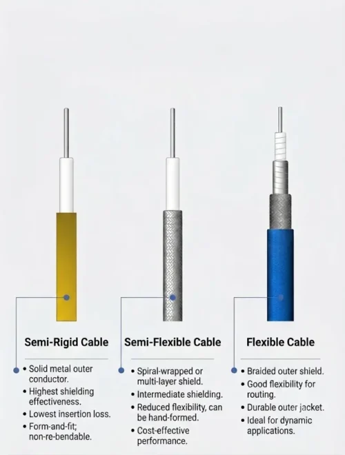
- Semi-Rigid: The outer conductor consists of a continuous, seamless metal tube. Once formed, it retains its shape and can barely bend further. Engineers call it “semi-rigid” rather than “fully rigid” because technicians can still bend it once during installation using specialized tooling — but after that single bend it sets permanently and cannot withstand repeated flexing.
- Semi-Flexible (Hand-Formable): The outer conductor uses a hand-formable braided structure, such as tin-dipped copper braid. It bends more easily than semi-rigid cable yet still holds its shape afterward, which is why the industry often calls it “hand-formable” cable. The term “semi-flexible” places it between the fixed form of semi-rigid cable and the free-bending nature of flexible cable.
- Flexible: The outer conductor uses braided mesh, aluminum foil, or multi-layer composite shielding, combined with a soft outer jacket. It can bend and move freely and repeatedly, giving it the highest flexibility of the three — hence the name “flexible.”
With this positioning in mind, let’s look at the fundamental differences in their internal structures.
1. Definitions and Structures of the Three Cable Types
The naming of these three cable types reflects how they behave when bent — that is, the degree of rigidity or flexibility they show during installation and operation.
Semi-Rigid Cable Assemblies
Semi-rigid cable assemblies use a solid silver-plated copper conductor (or copper-clad steel) as the center conductor, a polytetrafluoroethylene (PTFE) dielectric layer, and a continuous seamless metal tube as the outer conductor (typically copper tubing), usually without an outer jacket. Because the outer conductor forms a continuous, gap-free solid tube wall, it delivers shielding close to 100% and permanently holds its shape once formed — engineers sometimes call it a “one-time forming cable.”
Technicians must bend it using dedicated forming tools and cannot re-bend it repeatedly, or the outer conductor may work-harden and crack. Common outer diameters include 0.047, 0.085 (sometimes listed as 0.086 by some suppliers), 0.141, and 0.250 inches. Smaller 0.020 / 0.034 inch versions serve high-density millimeter-wave routing.
Semi-Flexible / Hand-Formable Cable Assemblies
This type offers a practical compromise between semi-rigid and fully flexible cable assemblies. Its internal structure resembles semi-rigid cable (solid center conductor, PTFE dielectric), but its outer conductor uses a solder-coated copper braid — the solder impregnates the copper braid so technicians can bend it by hand and it still holds its shape.
It requires no dedicated forming tool. Engineers can shape it manually, and it can be re-formed a limited number of times without noticeably degrading RF performance. This makes it ideal for prototypes where routing is still under adjustment but electrical performance still matters. Suppliers may offer it with or without an FEP jacket.
Flexible Cable Assemblies
Flexible cable assemblies use braided copper, aluminum foil, or multi-layer hybrid shielding as the outer conductor, along with an FEP/PE/PVC jacket. Among the three types, flexible cable bends best, withstands thousands of dynamic bend cycles, and installs most easily.
Standard RG-series braided shielding typically covers 85%–100%, so its shielding and insertion loss generally fall short of semi-rigid types. That said, high-performance flexible cables with high-density braid-plus-foil constructions can extend frequency coverage to 18 GHz and even beyond 60 GHz while maintaining good phase and amplitude stability after bending.
Overall, these three cable categories form a spectrum running from “ultimate electrical performance and mechanical stability” to “ultimate installation flexibility.” Semi-rigid delivers the best RF performance but is almost impossible to adjust after installation; semi-flexible balances performance and convenience; flexible cable prioritizes routing convenience and repeated movement, typically at some cost to shielding, loss, and phase stability.
2. RF Electrical Performance Comparison
The three types share the same core electrical parameters: characteristic impedance (typically 50 ohm, or 75 ohm for video/cable TV), insertion loss/attenuation (dB), VSWR/return loss, propagation velocity (VP), and power handling. Verification methods, though, differ by parameter:
- Engineers typically measure insertion loss, return loss/VSWR, phase, and delay with a vector network analyzer (VNA) using S11/S21.
- Shielding effectiveness gets verified through transfer impedance or shielding effectiveness testing.
- Passive intermodulation (PIM) requires a two-tone PIM tester, commonly under 2 x 43 dBm dual-carrier conditions.
- Power handling capability comes from thermal/power rating tests or calculations — not every parameter derives from S11/S21.
The differences show up in the details.
Shielding Effectiveness
The seamless metal tube of semi-rigid cable provides the strongest shielding; semi-flexible (solder-coated braid) shielding comes close to semi-rigid; standard flexible cable is limited by braid coverage, while high-performance flexible cable can match the first two using high-density braid-plus-foil structures. As a rough reference, semi-rigid cable typically achieves more than 90 dB within 40 GHz, and high-quality semi-flexible structures can reach more than 100 dB within 18 GHz, with some models exceeding 110 dB. Always check the manufacturer’s datasheet for exact values, and avoid applying one model’s numbers to an entire product category.
Phase Stability
Once formed, semi-rigid cable stays put, making it the benchmark for phase stability — that’s why phased-array radar and beamforming systems often favor phase-matched semi-rigid cables. Flexible cables, by contrast, may drift in amplitude and phase under repeated bending unless engineers specifically design them as “phase-stable.”
Phase stability depends heavily on cable model, temperature range, bend radius, test frequency, and test method, so treat it as a variable rather than a fixed spec across the three categories. As a general reference, PTFE-dielectric cables typically show phase change with temperature on the order of 600 ppm/°C, while phase-stable designs — whether semi-rigid or specialized flexible constructions — reduce phase error from bending and temperature through precise length control and a uniform dielectric structure. Always pull specific values from the manufacturer’s test report under the stated conditions.
Passive Intermodulation (PIM)
Braided structures contain many metal-to-metal contact points, which can introduce nonlinear noise. As a result, standard braided flexible assemblies are harder to guarantee for low-PIM consistency — a key concern in multi-carrier environments such as base stations and distributed antenna systems (DAS).
PIM performance, however, also depends strongly on connector type, plating, assembly torque, contamination, and installation stress, so “flexible always performs worse” oversimplifies the picture. For low-PIM applications, semi-rigid, corrugated, or dedicated low-PIM assemblies more consistently achieve PIM levels of -155 to -160 dBc, typically under 2 x 43 dBm dual-carrier conditions with a specified frequency band, torque, and clean connectors. Always base exact values on the manufacturer’s PIM test report for the specific power level and frequency band.
Frequency Range
Cable structure, outer diameter and mode cutoff frequency, dielectric, connector grade, and the full assembly’s test results — not just the connector — determine the maximum usable frequency. In some millimeter-wave families, small-diameter semi-rigid cable such as 0.047 inch can support 40–67 GHz, but this applies only to specific small-diameter or millimeter-wave series and doesn’t generalize to all semi-rigid cables. A 1.0 mm interface may theoretically reach 110 GHz, but that doesn’t mean any 0.047 inch assembly reaches that limit. Standard RG-series flexible cables typically max out at 3–6 GHz, while high-performance braided flexible cables can reach 18–67 GHz.
Comparison Table
| Aspect | Semi-Rigid | Semi-Flexible | Flexible |
|---|---|---|---|
| Outer conductor | Seamless copper tube | Solder-coated/tinned braid, optional foil | Braided shield + foil / multi-layer |
| Shielding | Strongest, nearly 100% | Close to semi-rigid (typically 100 dB+) | Standard types are limited; high-performance versions can match |
| Frequency limit | Determined by cable structure and connector; small-diameter millimeter-wave series can reach 67 GHz+ | Typically 18–40 GHz | RG types 3–6 GHz; high-performance 18–67 GHz |
| Phase stability | Best | Good | Drift under bending; phase-stable versions improve this |
| Minimum bend radius (rule of thumb) | One-time forming, 5–10x OD | Hand-formable, limited re-shaping | Dynamic bending, thousands of cycles |
| PIM | Easily reaches -155 to -160 dBc | Good | Standard braided versions are less stable; low-PIM designs required |
| Typical applications | Phased-array panels, satellite payloads, calibration references | Compact enclosure routing, prototypes, low-PIM jumpers | Test jumpers, ATE dynamic cables, feeder jumpers |
3. Mechanical Performance: Bend Radius and Assembly Reliability
Before discussing bend radius, it helps to distinguish three different concepts: the formed bend radius of semi-rigid cable (required during one-time shaping), the static installation bend radius of flexible cable (after installation, once it stops moving), and the dynamic flex life of movable flexible cable (how many bending cycles it can withstand). These metrics differ and shouldn’t be compared directly.
Semi-Rigid: Static, One-Time Forming
Technicians typically form semi-rigid cable once, using forming tools, a tube bender, or fixtures, and it doesn’t suit repeated re-bending. As a general industry rule, the minimum bend radius for different wall thicknesses and diameters usually runs around 5–10 times the outer diameter, depending on material and wall thickness. Bending it too tightly can wrinkle the outer conductor and create impedance discontinuities, and re-bending will almost always damage the outer conductor.
Notably, bend-radius tables in NASA-STD-8739.4 set the preferred bend radius for semi-rigid cable at 3.5x OD, with a minimum of 2x OD — actually smaller than for flexible cable, because the rigid structure doesn’t spring back once formed. That said, this figure applies to controlled forming processes, and the field still recommends a conservative 5–10x OD.
Flexible: Static Installation Bend Radius
For flexible coaxial cable, NASA-STD-8739.4 offers a common reference: a recommended bend radius of about 10 times the cable diameter for a single flexible coaxial cable, with a minimum allowable bend radius of about 6 times. Ten times is the safer recommendation; six times is the lower limit you shouldn’t exceed. IPC/WHMA-A-620 also specifies 10x OD for flexible coaxial cable, though coaxial cable secured against movement may drop to 5x OD. Small RF connectors also usually need a no-bend zone of 10–25 mm behind the connector. Always confirm final allowable values against the cable datasheet, connector datasheet, installation drawing, and RF test results.
Repeated Bending in Semi-Flexible and Flexible Cables
Semi-flexible cable usually tolerates only a few bends before the outer conductor starts to wrinkle, reducing shielding and impedance consistency. Flexible cable — especially models designed for continuous dynamic bending — can withstand thousands of bend cycles, making it ideal for test benches, robotic arms, and cable chains.
4. Typical RF Applications
Engineers commonly use semi-rigid cable assemblies in internal satellite payload links, interconnects between phased-array radar panels, precision test and measurement reference cables/calibration kits, and 5G millimeter-wave base station enclosures. These applications involve dense routing, no post-installation movement, and extremely high phase stability requirements.
Semi-flexible cable assemblies see the most use in prototype validation and low-volume preproduction, where the design is still evolving, routing may need fine adjustment, but electrical performance can’t take too big a hit. They also show up in avionics equipment, internal antenna array connections, and low-PIM RF jumpers such as DAS and low-intermodulation rack interconnects, where one or two on-site manual adjustments are often needed.
Flexible cable assemblies serve as the workhorse for lab test jumpers, ATE dynamic test leads, instrument interconnects, base station to antenna feeder jumpers, and interconnects in vibrating vehicle or airborne environments. In automated test systems especially, the cable must survive thousands of bend cycles with minimal amplitude and phase change — exactly the core use case for high-performance phase-stable flexible cable.
5. Selection Workflow: Five Steps
Rather than asking “which one is better,” follow these steps for a specific project:
- Determine the maximum operating frequency, then work backward to the required connector grade. SMA typically goes to 18 GHz, 3.5 mm to about 34 GHz, 2.92 mm (K) to 40 GHz, 2.4 mm to 50 GHz, 1.85 mm (V) to 67 GHz, and 1.0 mm (W) to 110 GHz.
- Calculate the full-link insertion loss / VSWR budget to determine whether the project needs a low-loss semi-rigid or semi-flexible structure, or whether flexible cable still has enough margin.
- Evaluate installation space and routing complexity: fixed routing calls for semi-rigid; a design still under iteration calls for semi-flexible; 3D obstructions or frequent rerouting call for flexible.
- Check dynamic motion, vibration, and low-PIM requirements. Multi-channel systems such as base stations and DAS should pay special attention to PIM and verify the combined impact of connector type, plating, torque, and installation stress.
- Balance cost and lead time. Semi-rigid requires tooling and engineering drawings, with higher labor and upfront development cost; flexible installs fastest, and standard solutions carry the lowest total cost, though phase-stable, low-loss, and low-PIM high-performance flexible cables can cost significantly more.
6. Common Sizes and Connector Reference
Common semi-rigid cable outer diameters include 0.047, 0.085 (or 0.086), 0.141, and 0.250 inches. Smaller 0.020 / 0.034 inch versions serve high-density millimeter-wave routing. The table below shows the relationship between connector grade and typical maximum frequency for reference only, since tolerances vary by supplier:
| Connector | Typical Maximum Frequency |
|---|---|
| SMA (SubMiniature version A) | DC–18 GHz; precision versions extend to 26.5 GHz |
| 3.5 mm | DC–34 GHz |
| 2.92 mm (K) | DC–40 GHz |
| 2.4 mm | DC–50 GHz |
| 1.85 mm (V) | DC–67 GHz |
| 1.0 mm (W) | DC–110 GHz |
Connector compatibility: SMA, 3.5 mm, and 2.92 mm belong to one family (1/4-36 UNS thread) and usually mate mechanically, though high-frequency performance may degrade and the interface may wear. 2.4 mm and 1.85 mm belong to another family (M7 thread) and usually mate as well. The 2.4 mm / 1.85 mm / 1.0 mm family generally can’t mechanically mate with the SMA / 3.5 mm / 2.92 mm series, and forcing a connection will cause permanent damage. When selecting components, treat the connector, cable, and adapter as one complete chain rather than looking at the cable datasheet alone.
7. FAQ
1.Can semi-rigid cable assemblies be bent repeatedly?
No. Once the solid outer conductor is formed, its shape stays fixed. Repeated bending causes metal fatigue or cracking, damages the shielding layer, creates impedance discontinuities, and leads to abnormal VSWR or signal loss. During assembly, use the proper tool to form the final shape in one step.
2. Is semi-flexible cable underestimated?
Many comparison articles give it only one line, but for compact enclosure routing it’s a very practical option: its electrical performance comes close to semi-rigid, its PIM performance holds up well, and it doesn’t require forming dies for every position. It especially suits fixed installations with limited space that still need minor on-site adjustment.
3. Can flexible cable match the shielding of semi-rigid cable?
Standard RG-series cables usually can’t match semi-rigid shielding, because of braid coverage limitations. However, high-performance flexible cables with high-density braid-plus-foil shielding are engineered for phase and amplitude stability during bending, and they can achieve shielding and insertion loss close to semi-rigid within specific frequency ranges — at a higher cost.
4. Why does flexible cable have higher insertion loss at high frequencies?
Current travels a more tortuous path through a braided outer conductor than through a continuous solid semi-rigid conductor, and braid coverage typically falls short of 100%, which increases resistive loss and some signal leakage. As frequency rises, the skin effect concentrates current on the conductor surface, so the effect of braid gaps on shielding and attenuation becomes more significant.
5. What are the most common causes of RF cable connector failure?
Non-standard assembly processes — such as improper soldering, crimping, or torque — excessive force or misalignment during mating, insufficient strain relief at the cable root leading to repeated fatigue, and metal fatigue or dielectric deformation from thermal cycling all gradually degrade VSWR and insertion loss.
6. How should you make the final choice among the three?
Choose semi-rigid when routing is fixed and phase stability plus high-frequency shielding matter most. When the design is still evolving and needs occasional on-site fine-tuning without sacrificing too much performance, semi-flexible offers the best compromise. For frequent movement, vibration resistance, or fast installation, flexible cable assemblies — standard or high-performance braided versions depending on frequency — are usually the practical choice.
Conclusion
Semi-rigid, semi-flexible, and flexible cable assemblies aren’t substitutes for one another — they represent different trade-offs for the same design problem: finding the right balance between electrical stability and mechanical flexibility. The reliable approach starts by defining the system’s frequency range, insertion loss / VSWR budget, low-PIM requirements, installation environment (vibration, repeated adjustment), and cost/lead-time constraints, then checking each item against the selection workflow above. At critical stages, ask the cable assembly supplier for measured S11/S21 curves, bending test data, and PIM test reports — these always prove more reliable than the datasheet alone.