




What is 2.92 mm Connector?

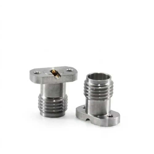
2.92mm connector is a precision RF/microwave coaxial connector with a 2.92mm outer conductor inner diameter, a 50Ω impedance, and mode-free operation from DC up to 40GHz (up to 46GHz in some high-frequency designs). Engineers more commonly call it the K connector, and its design keeps it mechanically compatible with SMA and 3.5mm connectors — which is exactly why engineers reach for it so often.
In fact, if you work anywhere near RF test benches, VNAs, radar systems, or 5G hardware, you’ve almost certainly handled one, whether or not you knew it by name.
So here’s everything you need to know about what it is, how it works, its specifications, and when to use it.
A Brief History: From MPC3 to the K-Connector
The 2.92mm interface didn’t start out with that name. In fact, Maury Microwave first introduced the geometry in the mid-1970s under the designation MPC3. However, there wasn’t much 40GHz test equipment around at the time, so the connector saw limited use.
That changed in 1983: Wiltron Co. (now part of Anritsu) built a line of instrumentation that reached 40GHz and needed a connector to match. Wiltron then trademarked the name “K-connector,” referencing the K-band of frequencies the connector covers. The name stuck, and today engineers use “2.92mm” and “K connector” interchangeably across the industry. You’ll also occasionally see it called an SMK connector.
Notably, mating compatibility with SMA wasn’t the original design goal. Instead, it came about because the 2.92mm interface borrowed proven SMA geometry, and that shared heritage turned out to be one of its biggest practical advantages.
How the 2.92mm Connector Works
So what actually makes the 2.92mm connector different from SMA? The core engineering trick is its air dielectric. Standard SMA connectors use a solid PTFE (Teflon) insulator at the mating interface, which limits reliable mode-free performance to around 18GHz — above that, unwanted higher-order waveguide modes start to interfere with the signal.
By contrast, the 2.92mm connector removes that solid dielectric from the mating plane and shrinks the outer conductor to exactly 2.92mm. As a result, the onset of those unwanted modes rises to roughly 40–46GHz, while the center pin’s dimensions maintain a clean 50Ω impedance in air rather than in PTFE.
Additionally, there’s one more deliberate design detail: the male pin on a 2.92mm connector is shorter than on an SMA or 3.5mm connector. This means the outer bodies of the male and female connectors make contact before the center pin and socket do, which reduces wear from misalignment during mating — a small mechanical choice that has a real impact on connector lifespan.
Key Specifications
The table below summarizes the core specs engineers reference most often:
| Parameter | Typical Value |
|---|---|
| Impedance | 50Ω |
| Frequency range | DC–40GHz (standard/Ultem dielectric); DC–46GHz (Kapton/high-frequency dielectric) |
| Insulation resistance | >5,000 MΩ |
| Contact resistance | ≤3.0 mΩ (center), ≤2.0 mΩ (outer) |
| Durability | 500+ mate/de-mate cycles |
| Voltage rating | Up to 250V AC operating; withstands 750V AC for 1 minute |
| Coupling thread | 1/4-36 UNS-2A (male) / 2B (female) |
| Body materials | Stainless steel or brass, often gold or passivated finish |
| Contact material | Beryllium copper |
| Standards | MIL-PRF-39012, MIL-STD-348, IEEE 287 |
That said, exact VSWR and insertion loss figures vary by manufacturer, cable type, and connector grade (general-purpose vs. metrology/lab-grade). Always check the specific datasheet for a given part rather than assuming a single spec applies across the board.
2.92mm Connector Dimensions
MIL-STD-348 (Figures 323-1 and 323-2) and IEEE 287 standardize the interface geometry, which is what allows different manufacturers’ 2.92mm connectors to mate reliably with each other. At a high level:
- Outer conductor inner diameter: 2.92mm (the number the connector is named for)
- Mating pin diameter: typically in the 0.0360–0.0368 inch (≈0.914–0.935mm) range, depending on the specific socket design
- Coupling thread: 1/4-36 UNS, identical thread pitch to SMA
- Panel/flange footprint: varies by mounting style — common flange options include 2-hole, 4-hole, 0.375″ square, 0.500″ square/long, and thread-in styles
Because the thread and general envelope match SMA, 2.92mm connectors often drop into existing SMA panel cutouts and footprints. Even so, always confirm the specific flange pattern against the manufacturer’s mechanical drawing before finalizing a design, since flange sizes do vary between vendors.
Male vs. Female (Plug vs. Jack)
Like most RF connectors, 2.92mm connectors come in male (plug, with the center pin) and female (jack, with the socket) versions:
- 2.92mm male connector: Has the protruding center pin. Used on cable ends, adapters, and many instrument test ports.
- 2.92mm female connector: Has the recessed socket. Common on bulkhead/panel mounts, PCB launch connectors, and some cable assemblies.
Gender selection depends entirely on what you’re mating to, so always check the gender of the port or cable on the other end of the connection before ordering.
Common 2.92mm Connector Structures
In practice, engineers typically select a 2.92mm connector by mechanical structure and installation method first, then confirm electrical specs. The main categories:
Cable mount connectors — Straight plug or jack connectors that manufacturers terminate onto semi-rigid, semi-flexible, or flexible 0.141″/0.085″-equivalent coaxial cable. These form the backbone of most 2.92mm cable assemblies for test and interconnect work.
Bulkhead / panel mount connectors — Similarly, a 2.92mm bulkhead connector passes through an enclosure wall or instrument front panel, providing a fixed, mechanically stable interface. It comes in 2-hole and 4-hole flange patterns, various flange sizes, and thread-in styles for chassis or module integration.
End launch PCB connectors — In addition, a 2.92mm end launch connector transitions a PCB microstrip or grounded coplanar waveguide (GCPWG) trace directly into a coaxial 2.92mm interface at the board edge. You’ll typically find these on evaluation boards, RF modules, and compact assemblies where board-to-cable transitions need to stay clean up to 40GHz+.
Vertical/solderless PCB connectors — Alternatively, compression-style connectors clamp onto a PCB without soldering, which is useful for prototype boards and repeatable test fixtures where components need to come on and off easily.
Adapters — Finally, 2.92mm-to-2.92mm, 2.92mm-to-SMA, 2.92mm-to-3.5mm, and 2.92mm-to-N-type adapters extend compatibility across connector families in mixed test setups.
2.92mm vs. SMA vs. 3.5mm vs. 2.4mm
This is one of the most common points of confusion, so here’s a direct comparison:
| Connector | Frequency Range | Dielectric | Mates With | Best For |
|---|---|---|---|---|
| SMA | Up to ~18GHz (some variants higher) | Solid PTFE | 3.5mm, 2.92mm | General-purpose RF, cost-sensitive designs, non-critical connections |
| 3.5mm | Up to ~26.5–34GHz | Air | SMA, 2.92mm | Lab-grade precision below 2.92mm’s ceiling |
| 2.92mm (K) | Up to 40GHz (46GHz variants) | Air | SMA, 3.5mm | High-frequency test, 5G, aerospace — the sweet spot between SMA and 2.4mm |
| 2.4mm | Up to 50GHz | Air | 2.4mm, 1.85mm only | Higher-frequency systems where 2.92mm doesn’t have enough margin |
In short, the key takeaway is this: SMA, 3.5mm, and 2.92mm all share the same 1/4-36 UNS thread, so they mate mechanically without much trouble. However, 2.4mm uses a different thread size and doesn’t mechanically fit the SMA/3.5mm/2.92mm family at all — it only mates with other 2.4mm or 1.85mm connectors.
Can You Mate a 2.92mm Connector with SMA?
Mechanically, yes — a 2.92mm connector will thread onto an SMA connector without issue, and the widely-cited 2007 Microwave Journal study on SMA/3.5mm/2.92mm intermateability formally confirmed this. Electrically, though, it’s a bit more nuanced.
What happens when you mate them:
- First, the connection works and won’t damage a connector in good condition on a single mate.
- However, the SMA side will limit performance above roughly 18GHz, since that’s the weaker link in the pair — so you won’t get 2.92mm-grade performance out of the combination.
- Because the air-dielectric 2.92mm connector meets the solid-PTFE SMA at the mating plane, there’s a small impedance discontinuity right at that junction, which shows up as increased VSWR/return loss compared to a same-family mated pair.
- Second, repeated mating matters more than a single connection. Manufacturers build standard SMA connectors to looser commercial tolerances than precision 2.92mm connectors, so frequent cycling with lower-grade SMAs can gradually wear the more precise threads and contacts on a 2.92mm port.
Best practice: for lab and metrology-grade 2.92mm ports — especially on VNAs from vendors like Keysight, Anritsu, or Rohde & Schwarz — use a dedicated “connector saver” (a sacrificial adapter) when regularly mating SMA cables or devices under test. It’s a cheap way to protect an expensive precision port from wear.
Typical Applications
In practice, 2.92mm connectors show up anywhere engineers need reliable, repeatable microwave performance up to 40GHz:
- RF and microwave test & measurement — VNA test ports, calibration kits, cable assemblies, and fixture interfaces
- 5G and wireless infrastructure — mmWave test setups and RF module interconnects
- Aerospace and satellite (SATCOM) — RF links where connector reliability and environmental performance matter
- Radar systems — microwave signal paths in radar and electronic warfare equipment
- PCB evaluation and validation — end-launch and solderless connectors on test/eval boards
- General lab and production test — anywhere SMA’s ~18GHz ceiling isn’t enough, but full 2.4mm-level frequency headroom isn’t needed either
How to Choose the Right 2.92mm Connector
A few practical steps to narrow down the right part:
- First, start with your frequency requirement. If you’re at or under 40GHz, standard 2.92mm connectors are usually sufficient. Need up to 46GHz? Look for high-frequency dielectric (e.g., Kapton) variants built specifically for it.
- Next, identify the mounting structure you actually need — cable mount, bulkhead/panel mount, end launch, or solderless PCB — before comparing model numbers. Otherwise, the right electrical spec on the wrong mechanical structure won’t fit.
- Then, confirm gender (male/plug or female/jack) against whatever it’s mating to.
- After that, check the mating environment. If the connector will regularly interface with commercial-grade SMA hardware, plan for connector savers to protect precision ports.
- Finally, match materials to your environment — stainless steel bodies for durability and repeated cycling, brass for cost-sensitive, lower-cycle applications.
FAQ
- What frequency range does a 2.92mm connector support?
Standard 2.92mm connectors operate from DC to 40GHz. In addition, high-frequency dielectric variants extend this to 46GHz.
2. Is a 2.92mm connector the same as a K connector?
Yes. “K connector” is the trade name Wiltron (now Anritsu) gave the 2.92mm interface in 1983, and engineers use the two terms interchangeably today.
3. What’s the difference between a 2.92mm connector and an SMA connector?
SMA uses a solid PTFE dielectric and typically reaches about 18GHz. The 2.92mm connector, on the other hand, uses an air dielectric, reaches 40GHz or higher, and has a shorter male pin — though both share the same thread size and mate mechanically.
4. Can 2.92mm connectors mate with SMA connectors?
Yes, mechanically. However, electrically, the SMA side of the connection will limit performance above ~18GHz, and frequent mating with lower-tolerance SMA hardware can wear precision 2.92mm ports over time. For repeated use, engineers should use a connector saver.
5. What is a 2.92mm end launch connector used for?
It transitions an RF signal from a PCB trace (microstrip or GCPWG) directly into a coaxial 2.92mm interface at the board edge — common on evaluation boards and RF module designs.
6. What is a 2.92mm bulkhead connector?
A bulkhead (panel mount) 2.92mm connector passes through an enclosure wall or instrument panel, providing a fixed, mechanically stable RF port. It’s typically available in 2-hole or 4-hole flange configurations.
7. Do 2.92mm connectors work with 2.4mm connectors?
No. 2.4mm connectors use a different thread size, so they only mate mechanically with other 2.4mm or 1.85mm connectors — not with SMA, 3.5mm, or 2.92mm.
Conclusion
The 2.92mm connector, which engineers more commonly call the K connector, earns its place in RF and microwave systems by hitting a practical sweet spot: it delivers precision performance up to 40GHz (and beyond, in high-frequency variants) while remaining mechanically compatible with the SMA and 3.5mm hardware most labs already have. Ultimately, understanding its air-dielectric design, its dimensional standards, and its intermateability quirks with SMA is what separates a connector choice that just “fits” from one that actually performs at the frequencies you need.