


MIL-DTL-5015 Insert Arrangement Guide
If you have ever tried to match a MIL-DTL-5015 connector to a cable harness drawing, you already know the real challenge is not the shell style alone. The hard part is the insert arrangement.
Two connectors can both be “MIL-DTL-5015, shell size 18,” and still be completely different inside. One may support a simple 10-contact signal layout. Another may be arranged for a mixed signal-and-power circuit set. On paper they look related. In practice, they are not interchangeable at all.
That is why the insert arrangement is one of the first things engineers, buyers, and harness builders need to confirm before ordering. It affects the number of circuits, the contact size, the mating pair, the polarization, and in many cases, the final wire termination method.
This guide is written for people who actually need to select or verify a connector, not just define the term. You will see how the numbering works, where people commonly misread the standard, how to think about contact size and current, and how to avoid the costly mistakes that lead to wrong parts, delays, or rework.
What Is an Insert Arrangement in MIL-DTL-5015
In plain language, the insert arrangement is the internal contact map of the connector.
It tells you:
- How many contact cavities are available.
- Where those cavities sit inside the rigid insert.
- What contact sizes the arrangement supports.
- Which contacts are pins and which are sockets.
The standardized insert layout system used for this connector family is defined by MIL-STD-1651. In practical engineering work, that means you should treat the arrangement number as a real specification item, not an optional detail.
Why Insert Arrangement Matters in Real Projects
Most connector problems in the field are not caused by picking the wrong shell style. They are caused by choosing the wrong internal layout.
A wrong insert arrangement creates several critical practical problems:
- The harness has more circuits than the connector can physically accept.
- The connector has enough contacts, but not enough current capacity.
- The plug and receptacle cannot form a correct mating pair.
- The panel uses identical connectors next to each other, leading to catastrophic mix-ups during assembly.
- The final system needs room for future circuits, but the selected arrangement has zero spare capacity.
That is why a reliable selection flow starts with the circuit requirement first, then the electrical load, and only then the shell size and arrangement.
How to Read MIL-DTL-5015 Arrangement Numbers
A MIL-DTL-5015 connector is identified by a military standard (MS) part number that includes the shell style, class, shell size, insert arrangement, contact gender, and alternate positioning.
A classic example looks like this:
MS3106A18-1P
Here is the practical reading order:
- MS3106: Connector style (e.g., Straight Plug).
- A: Class / Environmental style (General purpose, non-environmental).
- 18: Shell size (indicates the diameter of the connector body).
- 1: Insert arrangement code (the specific layout of the contacts).
- P: Pin contacts (S would indicate Socket contacts).
Important note: the arrangement number is not equal to the number of contacts. For instance, code 18-1 does not mean “18 minus 1” or “1 contact.” It is a standardized layout identifier that actually contains 10 cavities of Size #16 contacts. Never guess the contact count based on the number alone; always check the chart.
Technical Pillars: Decoding Contact Sizes & Voltage Ratings
To select an arrangement like an expert, you must look at the two underlying data sets defined by MIL-STD-1651: Amperage and Service Voltage.
1. Contact Size & Current Capacity
MIL-DTL-5015 excels at mixing different wire gauges within a single shell. The contact size dictates the maximum allowable current and wire compatibility:
| Contact Size | Compatible Wire Gauge (AWG) | Rated Amperage (Max) | Practical Use Case |
| Size #16 | 16 – 22 AWG | About 13 A, depending on manufacturer | Low-current control lines, sensors, logic signals. |
| Size #12 | 12 – 14 AWG | About 23 A, depending on manufacturer | Moderate power loops, actuators, and power supplies. |
| Size #8 | 8 – 10 AWG | About 46 A, depending on manufacturer | Serious power duty, smaller motor feeds. |
| Size #4 | 4 – 6 AWG | About 80 A, depending on manufacturer | Heavy power distribution lines. |
| Size #0 | 0 – 2 AWG | About 150 A, depending on manufacturer | Main power feeds, extreme-current applications. |
Note: Do not rely on universal amp tables blindly. Always check the specific manufacturer’s catalog for temperature rise and derating limits.
2. Service Voltage Ratings
The spacing between contacts determines the connector’s safe operating voltage. When checking an arrangement layout, look for its Service Rating letter code:
- Inst. (Instrument): 200 VAC RMS / 250 VDC, typically used for low-level sensor and signal lines.
- A (Standard): 500 VAC RMS / 700 VDC, one of the most common ratings for general industrial machinery.
- D (Heavy Power): 900 VAC RMS / 1250 VDC, used for heavier industrial power and motor-drive applications.
- E (High Voltage): 1250 VAC RMS / 1750 VDC.
- B (Extreme Voltage): 1750 VAC RMS / 2450 VDC.
Alternate Insert Positions: Preventing Mismating Disasters
If multiple identical connectors (same shell size and same layout) are mounted close together on a control panel, a technician can accidentally plug Cable A into Port B. This causes wiring confusion, commissioning delays, or immediate equipment damage.
To solve this, MIL-DTL-5015 utilizes Alternate Insert Positions (Insert Rotation).
While the master keyway on the outer shell remains fixed, the entire internal plastic/rubber insert is rotated relative to the shell. These positions are designated by letters: W, X, Y, and Z.
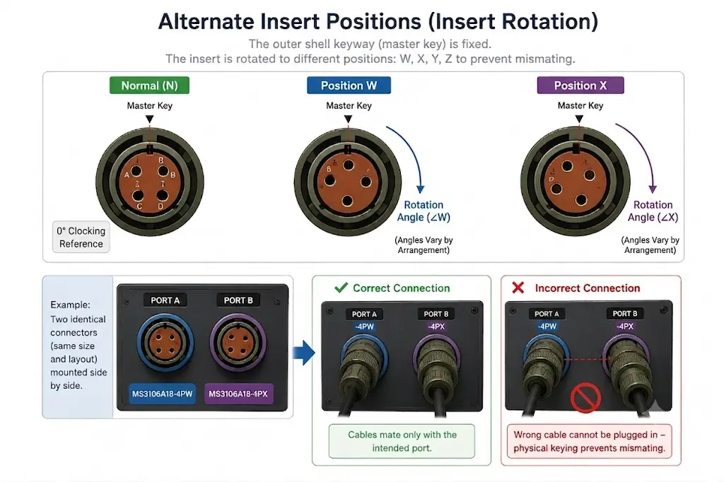
However, not every insert arrangement offers the same set of alternate positions. The exact rotation options must always be verified against the arrangement chart.
By specifying MS3106A18-1PW for Port A and MS3106A18-1PX for Port B, you guarantee a physical, foolproof lock—the wrong cable physically cannot be plugged into the wrong port.
Common Insert Arrangement Examples You Will See Often
Rather than looking at thousands of choices, these five classic layouts solve 80% of industrial and harness problems:
- 12S-3 (2 Contacts, Size #16): Perfect for compact, 2-wire low-count sensor loops or micro-switches.
- 16S-1 (7 Contacts, Size #16): The gold standard for low-power, multi-channel control signals in compact enclosures.
- 18-1 (10 Contacts, Size #16): Widely used general-purpose signal layout for industrial automation harnesses.
- 20-27 (14 Contacts, Size #16): A denser signal layout when you need more control circuits routed through a single panel cut-out.
- 22-14 (19 Contacts, Size #16): Highly dense control layout. Excellent for connecting complex PLC systems where space is at a premium.
The Engineer’s 4-Step Selection Workflow
To guarantee a clean bill of materials, follow this structured sequence instead of guessing by shell size:
Step 1: Audit Circuits  ➔  Step 2: Map Current  ➔  Step 3: Verify Voltage  ➔  Step 4: Lock Model & Options
(Count Power vs Signal)     (Choose Contact Size)    (Check Service Rating)     (Select Rotation/Termination)
- Audit Your Circuits: Count your total required lines and separate them by Power vs. Signal (e.g., 3 power lines, 4 signal lines = 7 lines total).
- Size the Amperage: Match your currents to the correct contact sizes (e.g., 3 lines need 20A – Size #12; 4 lines need 3A – Size #16).
- Verify the Voltage: Cross-check the arrangement’s Service Rating (Inst, A, D) against your system’s working voltage.
- Lock the Full Part Number: Ensure the selected arrangement mechanically fits within your physical panel space, choose your contact gender, and add insert rotation if needed.
Procurement Checklist & Critical “F-O” Trap
Before passing a part number to your purchasing department, confirm these final variables:
- Termination Style: Do you need Solder cups (best for field repairs and low-volume) or Crimp contacts (best for high-volume automated line assembly)?
- Environmental Class: Will it sit in a dry cabinet (Class A), or does it face heavy vibration and liquid washdowns (Class F / Environmental with a sealing grommet)?
- Contact supply: whether contacts are included or must be ordered separately.
Notes: Watch out for part numbers ending in -FO or L/C (e.g., MS3106F20-27S-FO). This stands for “Force Out” or “Less Contacts”. It means the connector will ship completely empty without any metal pins or sockets. If your team does not order the contacts separately, assembly will grind to a halt.
Summary: What Mistakes Cause the Most Rework?
- Choosing by shell size only: Assuming any size 18 connector will plug into your size 18 cable end.
- Assuming layout codes equal contact counts: Ordering an 18-1 thinking it has 1 pin instead of 10.
- Forgetting environmental classes: Using a non-sealed Class A plug in a wet, outdoor vehicle harness.
- Ignoring insert rotation on multi-port panels: Leading to field technicians cross-wiring critical control systems.
A proper MIL-DTL-5015 insert arrangement selection keeps your engineering clean, your procurement accurate, and your field installations flawless. If you are drafting a new wire harness blueprint, always start with the electrical load, respect the MIL-STD-1651 layouts, and verify your part numbers with a certified manufacturer catalog.
FAQ
- What is an insert arrangement in MIL-DTL-5015?
- It is the standardized internal contact layout of the connector. It dictates the exact cavity pattern, supported contact sizes, and mating behavior within the shell.
2. Why does the insert arrangement matter so much?
Because shell size only defines the outer body. Two connectors can have the exact same shell size but entirely different internal layouts, meaning they are not physically or electrically interchangeable.
3. Does an arrangement code like “18-1” mean it has only one contact?
No. The arrangement code is a standardized identifier, not a contact count. For example, the 18-1 arrangement actually contains 10 cavities for Size #16 contacts. Always verify the count against an official layout chart.
4. What is the purpose of alternate insert positions (W, X, Y, Z)?
They prevent accidental mismating when identical connectors are mounted side by side. By rotating (clocking) the internal insert pattern relative to the fixed master keyway, you ensure that a cable can only plug into its designated port.
5. Can I rely on a generic amp rating table for all 5015 connectors?
No. Safe current capacity depends heavily on the specific manufacturer’s contact construction, materials, and temperature rise limits. Always verify ratings in the supplier’s exact datasheet.
6. Do all MIL-DTL-5015 insert arrangements offer W, X, Y, and Z rotation options?
No. Available alternate positions and their specific rotation angles vary significantly depending on the shell size and specific insert pattern. These must be checked case-by-case in the manufacturer’s catalog.