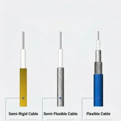
Semi-Rigid vs Semi-Flexible vs Flexible Cable Assemblies: Selection Guide
In microwave, millimeter-wave, 5G, satellite communication, and test systems, RF cable assemblies are far more than “just a wire.” Engineers

20 Years Manufacturer
Customization Support
Absolute Reliability: We guarantee MTBF rates exceeding 1 million hours under rated conditions.
Speed & Flexibility: From RFQ to delivery in as little as 3 weeks.
Global Support: 24/7 technical hotline and on-site engineers in five offices.
Regulatory Confidence: ISO 9001, AS 9100, IATF 16949 certified.

HUADA GROUP specializes in the R&D and production of mid-to-high-end optical, electrical, and fluid interconnection technologies. With over 200 proprietary product series and 10,000+ customizable configurations, we engineer mission-critical solutions for aerospace, defense, telecommunications, automotive, and rail industries.
Our products integrate triple-proof capabilities (waterproof, dustproof, corrosion-resistant) alongside high-density, ultra-reliable, and EMI-optimized designs, ensuring flawless performance in extreme environments.

Since 2002, HUADA GROUP has emerged as a global leader in smart sensor systems and industrial connectivity solutions, serving clients across automotive, IT, manufacturing, and energy sectors. Headquartered in Beijing with regional hubs across China and international offices, we combine cutting-edge R&D (15+ centers worldwide) with 200+ patented technologies to deliver precision-engineered products.


When designing or maintaining electrical interconnect systems for harsh environments, specifying the correct miniature circular connector is a critical phase. Within the high-reliability industrial and defense framework, the MIL-DTL-26482 specification establishes the standards for environment-resisting, quick-disconnect circular connectors. However, a recurring challenge during component selection is defining the exact operational boundaries between Series 1 and Series 2.
The two series belong to the same specification family and can intermate under defined conditions, but they are not universally interchangeable. A wrong cross-reference can lead to mating errors, accessory mismatch, or unnecessary rework on a wire harness layout. This technical guide outlines the core functional differences, accessory compatibilities, and selection parameters to ensure compliance with relevant industrial standards.
The MIL-DTL-26482 specification governs environment-resisting, quick-disconnect, miniature, circular electrical connectors utilizing a 3-point bayonet coupling mechanism. This design provides rapid mating and resistance to decoupling under vibration, making it a standard choice in commercial aerospace, military ground systems, and industrial instrumentation.
MIL-STD-1669 defines the insert arrangements for these connectors, ensuring that pin densities and geometric patterns remain uniform across manufacturers. While the specification establishes a unified front-end bayonet coupling footprint, the standard splits into two distinct series that vary in internal contact architecture, thermal categories, and rear accessory interfaces.
MIL-DTL-26482 Series I represents the foundational branch of this miniature circular family. As the Defense Logistics Agency (DLA) standard supplements detail, Series I historically centered on solder contacts, though the specification scope also defines front-release crimp removable variants.
In a standard Series I configuration utilizing fixed contacts, the factory pre-bonds the pins directly into a resilient rubber insulator insert.
This fixed solder-cup design provides high contact rigidity for permanent installations where engineers do not anticipate field modifications. Standard Series I configurations typically fall within a maximum temperature class of +125 ℃. Field repair of the solder variant generally requires precise hand-soldering or complete replacement of the connector housing assembly.
MIL-DTL-26482 Series II focuses on rear insertable and rear releasable crimp removable contacts to streamline assembly and field-maintenance requirements.
Instead of factory-bonding the contacts, technicians crimp them onto the conductor independently using standardized tools, such as the M22520 series. Technicians then push the contacts into the housing from the rear, where internal beryllium copper retention clips lock them into place.
This design allows for contact replacement from the rear without disturbing the surrounding wire harness. Depending on the qualification class, finish, and specific part number, Series II connectors fall into +175 ℃ or +200 ℃ operating categories. Hermetic configurations within Series II can accommodate either nonremovable solder type contacts or crimp removable terminations, depending on the exact part number selected.
The key parameters distinguishing the two series appear in the matrix below for rapid cross-referencing.
| Technical Parameter | MIL-DTL-26482 Series I | MIL-DTL-26482 Series II |
| Official Definition | Connectors, Solder Contact, Bayonet Coupling | Connectors, Crimp Contact, Rear Insertable / Releasable |
| Contact Style | Predominantly fixed solder contacts (front-release crimp variants exist) | Rear-release crimp removable contacts (hermetic variants offer solder/crimp options) |
| Hermetic Availability | Qualified standard configurations exist | Qualified standard configurations exist |
| Intermateability Limits | Restricted to Power Contacts Only | Restricted to Power Contacts Only |
| Standard Temperature Classes | Max +125 ℃ category | +175 ℃ or +200 ℃ categories (depends on class and part number) |
| Accessory Coupling Interface | Series-specific interface threads | AS85049 style accessory systems (requires print verification) |
The operational profiles of each series guide their deployment in modern systems:
The specification makes one limitation clear regarding intermateability: The two series can intermate when using standard power contacts, but shielded contacts do not intermate across generations. If your specific insert arrangement under MIL-STD-1669 includes shielded coaxial or triaxial lines, the physical dimensions and mating depths do not align. Avoid mixing Series I and Series II shells on the same interconnect line if data transmission or high-frequency shielded signals are involved.
Additionally, remember that the interfacial environmental seals differ. Mating a Series I plug to a Series II receptacle changes the design compression of the internal elastomer inserts, which can alter seal degradation profiles under extreme thermal cycling.
Neither Series I nor Series II provides full scoop-proof protection. If a technician angles a plug incorrectly during a blind-mating sequence, the front lip of the shell can strike and bend the male pins inside the mating half. To minimize pin damage during blind mating, configure the stationary bulkhead receptacle with female socket contacts and the movable cable plug with male pins. Recessed socket contacts reduce the probability of damage during rough handling.
Q1: What parameters must engineers verify on the drawing before ordering any accessory or replacement backshell?
Verify the exact shell size, series designation, and the rear accessory thread pitch. Do not assume an AS85049 backshell will properly thread onto a Series I shell unless the manufacturer datasheet or application drawing explicitly specifies a cross-compatible adapter interface for that exact part number.
Q2: What should engineers check first when verifying cross-series intermateability for an existing deployment?
Check the contact types within the insert arrangement under MIL-STD-1669. If the arrangement contains shielded, coaxial, or triaxial contacts, the plug and receptacle do not intermate across series unless the specific arrangement explicitly carries that qualification. Intermateability remains standard for power contacts only.
Q3: When should a designer still choose Series I for new equipment designs?
Series I remains preferred when the design requires a highly compact rear envelope without the added length of rear contact retention clips, when the wire assembly requires mandatory hand-solder termination, or when matching legacy bulkhead cutouts on existing instruments.
Q4: Why do shielded contacts require a dedicated arrangement designator?
Shielded contacts utilize different physical profiles and mating depths compared to standard power contacts. Under MIL-STD-1669, the standard isolates insert arrangements for shielded contacts and assigns distinct designators to prevent physical interference during shell mating.
Validating an interconnect architecture requires cross-checking part numbers, insert arrangements, and environmental finishes against active military sheets and manufacturer drawings. If you are cross-checking a replacement part, verifying an application-specific temperature class, or validating a complex insert arrangement under MIL-STD-1669, our engineering team can help review the specific series, contact style, and interface requirements to ensure a reliable deployment.

HUADA GROUP is a China-based manufacturer and global supplier of electrical connectors, cable assemblies, and sensor solutions. We provide reliable products and custom engineering support for aerospace, defense, data centers, rail transit, and power applications.
In microwave, millimeter-wave, 5G, satellite communication, and test systems, RF cable assemblies are far more than “just a wire.” Engineers
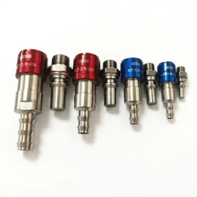
If you’ve spent any time researching liquid cooling for AI servers, you’ve run into the term UQD. It shows up
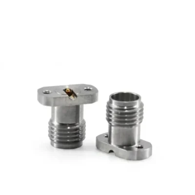
2.92mm connector is a high-precision RF and microwave coaxial connector designed specifically for high-frequency applications. Key features include an outer


Recent Comments