




MIL-DTL-38999 Series I vs II vs III vs IV: Complete Connector Comparison Guide

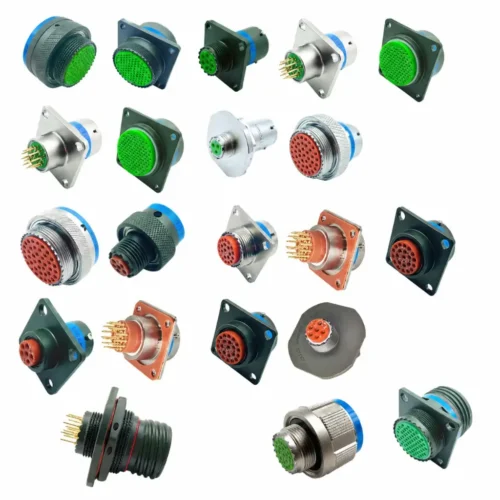
MIL-DTL-38999 is not just another standard connector in the commercial market. Instead, it serves as the absolute backbone of reliable connectivity across military aerospace, tactical defense systems, and rugged industrial environments where system failure is never an option. Specifically, this foundational specification defines four distinct series—I, II, III, and IV—whose technical variations go far beyond mere cosmetic differences. In fact, each individual series introduces fundamentally unique coupling mechanisms, specialized vibration profiles, distinctive EMI shielding characteristics, and critical environmental ratings.
Choosing the wrong series can quickly lead to catastrophic connector failure in the field, severe signal integrity degradation, or costly layout redesigns. To prevent these issues, this comprehensive guide provides the technical depth and exact performance data that hardware engineers need to make highly informed component selections.
What Is MIL-DTL-38999?
MIL-DTL-38999 (frequently referred to as D38999) represents a U.S. Department of Defense Detail Specification governing miniature, high-density, circular, environment-resistant electrical connectors. Importantly, the MIL-DTL designation indicates that this is a strict military detail specification, which explicitly defines precise baseline requirements for design, manufacturing, and qualification testing.
Unlike standard commercial-grade interconnects, qualified D38999 components must pass rigorous lab validations. For example, these tests include:
- Vibration testing: Continuous random vibration cycles from 50 to 2000 Hz, with varying g-level requirements tailored to each specific series.
- Mechanical shock testing: Severe half-sine wave shock pulses spiking up to 100g.
- Thermal cycling: Uninterrupted operation from -65°C to +200°C depending on the selected shell material and plating type.
- Salt spray corrosion testing: Up to 500 hours of continuous exposure for traditional cadmium-plated aluminum housings, extending up to 2000 hours for specialized composite materials.
- Mating durability: A minimum lifecycle of 500 complete mating/unmating actions for Series III aluminum assemblies, and up to 1500 cycles for composite variants.
- Insulation resistance: Sustaining a minimum of 5000 MΩ at room temperature.
Regarding the internal layout, these assemblies utilize removable, rear-release crimp contacts governed by the SAE AS39029 standard. Furthermore, contact sizes range from heavy-duty size 4 power pins down to ultra-fine size 22D or size 26 signal sockets. Depending on your spatial constraints, shell sizes span from #8 to #25, accommodating up to 128 discrete channels within a single interface.
MIL-DTL-38999 Series I Connectors
Mechanical Design and Coupling Mechanism
Series I relies on a robust three-position bayonet coupling mechanism to achieve secure mating. To operate this system, a technician simply pushes the connector plug into the matching receptacle and rotates the outer coupling nut approximately 90 degrees. Consequently, the internal bayonet lugs lock smoothly into the machined cam slots without requiring specialized hand tools.
In addition to speed, this bayonet configuration incorporates clear tactile and visual mating indicators. As the user turns the nut, three integrated lugs glide along matching tracks on the receptacle shell until hitting a hard mechanical stop. Therefore, the operator receives immediate physical feedback confirming a positive lock.
- Coupling rotation: Exactly ~90 degrees from an unmated state to a fully locked position.
- Axial retention force: A minimum of 15 lbs pull-out resistance when fully mated.
- Vibration threshold: Qualified for steady random vibration up to 20g RMS.
- Shock resistance: Rated to survive up to 40g half-sine shock waves (11ms pulse duration).
Scoop-Proof Design
A primary structural benefit of Series I is its 100% scoop-proof architecture. Under this design, the delicate contact pins are recessed deeply within the protective shroud of the plug shell. As a result, during blind or angled mating attempts, the outer shell of the receptacle makes contact with the protective shroud first. This physical barrier effectively guides the pins into alignment before they can touch the matching sockets, eliminating the risk of bent or shorted contacts.
Typical Applications and Trade-offs
Series I is perfectly suited for rugged applications demanding rapid disconnection and blind-mating ease. Typical deployments include:
- Marine electronics: Fleet navigation bridges and exposed shipboard radar systems subject to heavy salt spray.
- Tactical weapon systems: Ground defense equipment requiring fast, toolless cable swaps in frantic field conditions.
- Portable test kits: Diagnostic fields packs subjected to frequent deployment cycles.
However, certain engineering trade-offs must be evaluated. First, bayonet interfaces are inherently less secure than threaded counterparts when exposed to severe multi-axis harmonic vibration. Second, they are not rated for continuous vibration tracking above 20g RMS.
MIL-DTL-38999 Series II Connectors
Mechanical Design and Coupling Mechanism
Series II implements a specialized low-profile bayonet coupling structure. Although the underlying locking logic mirrors the Series I design, this alternative features a significantly reduced physical envelope. By compressing the coupling nut engagement length, designers managed to reduce the total connector length by approximately 15% to 20%.
- Physical envelope: Shorter profile and 10% to 15% lighter than a Series I variant of the identical shell size, minimizing the rear panel space requirement.
- Vibration threshold: Restricted to lower random vibration environments up to 10g RMS.
- Mechanical shock limit: Rated up to 25g half-sine shock pulses.
Critical Limitation: Not Scoop-Proof
Unlike the other three series, Series II is NOT scoop-proof. Because the contact pins are not deeply recessed within the shell shroud, there is no protective outer alignment ring to prevent angled impacts during installation.
Consequently, this structural deviation introduces severe operational risks:
- Pin damage hazard: Mating the shells at an improper angle can instantly bend or break the pins.
- Reduced cycle life: Internal testing reveals contact bowing or tracking wear after just 100 to 150 cycles.
- Field restriction: For these reasons, Series II is poorly suited for dark, muddy, or frantic field maintenance scenarios.
Therefore, deployment of Series II should be strictly restricted to internal, semi-permanent equipment racks where technicians can guarantee perfect visual alignment during initial integration.
Material and Plating Options
To optimize strength-to-weight ratios, Series II shells are typically machined from high-yield Aluminum alloy 7075-T6 or premium Titanium alloy Ti-6Al-4V. To illustrate the weight differences, consider a standard shell size #19:
- Series I Aluminum baseline: 45g
- Series II Aluminum alternative: 38g (Achieving a 15% weight savings)
- Series II Titanium premium tier: 28g (Delivering a 38% weight reduction over Series I)
MIL-DTL-38999 Series III Connectors
Mechanical Design and Coupling Mechanism
Series III incorporates a high-performance triple-start ACME thread coupling mechanism bundled with an integrated self-locking ratchet system. This configuration represents the most significant design evolution within the entire D38999 family, moving entirely away from the older bayonet locking styles.
Mechanically, this thread profile relies on three unified engineering characteristics:
- Rapid advance: The steep 30-degree lead angle allows the plug to move forward three times faster per turn than standard single-start threads.
- Anti-decoupling ratchet: An internal, spring-loaded ratchet wheel creates a distinctive, continuous clicking sound during installation, locking the nut at every increment to prevent backing out under heavy harmonic load.
- Visual indicator window: A high-visibility full-mate band on the receptacle offers instant visual confirmation that the connection is secure.
- Coupling rotation: ~120 degrees of turn required to reach a complete lock.
- Axial retention force: A minimum of 50 lbs pull-out resistance (A massive 3x increase over Series I).
- Vibration resistance: Withstands 44g RMS random vibration, making it the highest-rated baseline connector in the family.
Why Threaded Coupling Matters for Vibration
To understand the value of this design, we can analyze standard environmental stress testing. During a controlled test under MIL-STD-202 criteria:
- Series I (Bayonet): Exhibits coupling nut relaxation and electrical micro-fretting at 20g RMS, with total physical uncoupling occurring near 25g RMS.
- Conversely, Series III (Threaded): Maintains absolute electrical continuity at 44g RMS, handling peak localized spikes up to 50g without backing off.
This superior performance happens because the triple-start thread establishes continuous mechanical contact across the entire circumference of the shell. In contrast, bayonet configurations concentrate all mechanical stress onto three tiny pins, which can wear down over time under intense vibration.
Material and Plating Selection Matrix
Furthermore, Series III provides the most comprehensive array of materials, including robust composites, to solve diverse engineering challenges:
| Plating Material / Finish | Standard Thickness | Salt Spray Corrosion Resistance | Maximum Temperature Limit | RoHS Status |
| Black Zinc Nickel (DZ/ZR) | 0.0003″ (7.5 μm) | 1000 Hours | +200°C | Compliant |
| Olive Drab Cadmium (W) | 0.00015″ (3.8 μm) | 500 Hours | +175°C | Non-Compliant |
| Electroless Nickel (F) | 0.0002″ (5 μm) | 48 Hours (Inland Use) | +200°C | Compliant |
| Passivated Stainless Steel (K/S) | N/A (Solid Shell) | 1000 Hours (Firewall Rated) | +200°C | Compliant |
| Composite Olive Drab Cadmium (J) | N/A (Composite Base) | 2000 Hours | +175°C | Non-Compliant |
| Composite Electroless Nickel (M) | N/A (Composite Base) | 2000 Hours | +200°C | Compliant |
The Rise of Composite Shells (Class J & M) in Series III
While traditional aluminum and stainless steel shells remain industry staples, modern defense aerospace and unmanned aerial vehicle (UAV) designs heavily favor composite materials.
Engineers select composite variants to solve two critical engineering roadblocks:
- Massive Weight Reduction: Composite shells deliver a 17% to 40% weight savings compared to aluminum, and up to 70% weight savings compared to passivated stainless steel. This directly maximizes the flight endurance and payload capacity of airborne platforms.
- Extreme Corrosion Resistance: Unlike aluminum housings that survive 48 to 500 hours of salt spray, qualified composite connectors naturally withstand an extraordinary 2000 hours of continuous salt spray exposure without structural degradation.
MIL-DTL-38999 Series IV Connectors
Mechanical Design and Coupling Mechanism
Series IV features a specialized breech-lock coupling mechanism, which sets it apart from the other three configurations. In essence, this unique design combines the rapid manual installation speed of a bayonet with the heavy mechanical strength of a threaded interface.
Operationally, the mating sequence consists of two swift motions:
- Axial engagement: The technician pushes the plug straight along its axis into the receptacle until it hits a solid seat.
- Short turn locking: Rotating the nut just 60 to 90 degrees engages heavy-walled internal breech lugs, which click securely into place.
- Breech release mechanism: To unmate the assembly, the user simply presses an outer release collar downward while reversing the short turn.
- Coupling throw: A short 60 to 90-degree turn (The shortest travel distance among the heavy-duty variants).
- Vibration threshold: Rated for extreme 50g+ RMS random vibration environments.
- Acoustic noise threshold: Qualified to survive up to 140 dB of acoustic noise, making it ideal for mounting near rocket stages.
Why Breech-Lock Is Effective for Modular Payloads
When evaluating modular avionics pod swaps, the efficiency of this breech-lock design becomes highly apparent. For comparison:
- Series III (Threaded): Demands 3 to 5 seconds of manual turning time and a full 120-degree wrist rotation.
- In contrast, Series IV (Breech-Lock): Mates securely in under 2 seconds with a quick flick of the wrist. Additionally, because internal machined blocks stop the locking travel, it completely eliminates the risk of over-tightening.
How to Choose the Right MIL-DTL-38999 Series
Decision Framework Based on Application Requirements
Step 1: Analyze the Vibration and Acoustic Environment
- If your operational profile exceeds 10g RMS, eliminate Series II immediately.
- If your profile sits between 20g and 44g RMS, specify Series III as your baseline choice.
- Alternatively, if your system is mounted next to a rocket booster fairing encountering vibration profiles above 44g RMS, specify Series IV.
Step 2: Establish Total Lifecycle Mating Durability
- If the connection will be cycled more than 150 times over its service life, eliminate Series II.
- Conversely, if your application requires 500+ reliable cycles, Series III and IV are your only viable options.
Step 3: Check Specific Pin-and-Socket Coding Logic
To eliminate high-cost error rates during harness assembly, never rely on generic description tags. Always standard-verify your part number’s internal configuration codes:
- ZJ Code: Explicitly designates a Receptacle loaded with Male Pins.
- ZK Code: Explicitly designates a Receptacle loaded with Female Sockets.
Cross-checking the ZJ/ZK designation against your enclosure schematic ensures alignment and absolute signal continuity before the BOM reaches the factory floor.
Step 4: Implement Master/Alternate Keying (Polarization) to Prevent Cross-Mating
When designing high-density control panels where multiple connectors of the identical shell size and contact arrangement are mounted side-by-side, physical mis-mating poses a severe catastrophic risk to system electronics.
To eliminate this human error during field maintenance, MIL-DTL-38999 incorporates a highly reliable Master and Alternate Keyway Polarization Mechanism (designated by letters N, A, B, C, D, and E at the end of the standard part number).
- How it Works: The connector plug features a master key and four alternate keys that must align perfectly with the corresponding master and alternate keyways machined into the receptacle shell.
- Engineering Practice: By altering the rotational angles of these internal keys (e.g., using an ‘A’ position for Subsystem 1 and a ‘B’ position for Subsystem 2), the plug from Subsystem 1 will be physically blocked from engaging with the receptacle of Subsystem 2.
- BOM Coordination: Always align this polarization code alongside your pin-and-socket configuration logic. For instance, ensure your Bill of Materials (BOM) specifies whether a ZJ code or a ZK code requires a Normal (N) or an Alternate (A, B, C, D, E) keying rotation to guarantee error-free, drop-in integration on the manufacturing floor.
Backshell Selection for MIL-DTL-38999 Connectors
The connector housing is only half of the interconnection loop. In fact, your system’s overall environmental and electrical performance depends heavily on choosing the correct backshell accessory.
Backshell Styles and Selection Criteria
- Straight Environmental Backshells: Ideal for direct, unconstrained cable routing out of flat enclosures. However, they require an external bend clearance of at least 6x the total cable diameter.
- 90° Right-Angle Backshells: Perfect for tight space envelopes behind shallow control panels. Additionally, they reduce the cantilevered stress placed on the connector threads under multi-axis vibration.
- 360-Degree EMI Shielding Backshells: Essential for high-frequency signal lines with strict electromagnetic compatibility (EMC) targets. Specifically, these components use integrated ground rings or termination bands to clamp the cable braid directly to the connector shell, maintaining the critical shielding path greater than or equal to 65 dB.
Backshell Torque Specifications
Maintaining proper installation torque is crucial. Specifically, under-torquing leads to loose backshells, while over-torquing can permanently strip aluminum or composite threads.
| Connector Shell Size | Aluminum Backshell Torque Target | Stainless Steel Backshell Torque Target |
| #9 to #11 | 8–10 in-lbs | 10–12 in-lbs |
| #13 to #15 | 10–12 in-lbs | 12–15 in-lbs |
| #17 to #19 | 12–15 in-lbs | 15–18 in-lbs |
| #21 to #23 | 15–18 in-lbs | 18–22 in-lbs |
| #25 | 18–22 in-lbs | 22–28 in-lbs |
FAQ
1: What is the most common MIL-DTL-38999 series used in modern designs?
Series III is the most widely specified option in the global market. This popularity stems from its triple-start thread handling 44g RMS vibration, its broad array of RoHS-compliant platings, and its compliance with commercial aerospace standards like Boeing BACC63.
2: Can you mate a Series I plug with a Series II receptacle?
No. The series are not intermateable due to different shell diameters, keyways, and bayonet pin counts. Attempting to force them together will destroy the internal contacts.
3: What is the best RoHS-compliant alternative to traditional olive drab cadmium plating?
Black Zinc Nickel (Plating Code: DZ or ZR) is the ideal choice. Specifically, it delivers 1000 hours of salt spray corrosion resistance and excellent electrical conductivity while fully complying with global environmental laws.
4: What are the differences between standard crimp contacts and PC tail contacts for MIL-DTL-38999 connectors?
Standard crimp contacts conform to SAE AS39029 and utilize a specialized crimp tool to terminate stranded wire, providing excellent strain relief and flexible cable routing in harsh environments. In contrast, PC tail (Printed Circuit) contacts feature rigid, non-flexible solid tails that extend from the rear of the connector to solder directly onto a PCB interface. PC tail connectors eliminate backshells and wire harnesses entirely, which significantly minimizes weight and space inside sealed electronic enclosures, though they sacrifice the field-repairability inherent to rear-release crimp systems.
5: Can Series III composite connectors be mixed with aluminum or stainless steel backshells?
While physically possible because they share identical interfacial and rear accessory metric threads (MIL-DTL-38999 Series III uses metric threads exclusively, unlike the unified threads on Series I and II), mixing materials introduces severe galvanic corrosion risks. When a highly conductive aluminum backshell contacts a carbon-filled composite shell, the galvanic potential difference accelerates aluminum oxidation in coastal or marine settings. To maintain system integrity and survive the rated 2000 hours of salt spray, you must pair composite shells with matching composite backshells or highly passive stainless steel accessories.
6: How does the shell-to-shell conductivity requirement impact EMI shielding effectiveness across the series?
Shell-to-shell conductivity measures the electrical resistance across mated connector housings, which directly dictates how effectively high-frequency electromagnetic interference (EMI) is diverted to ground. Series III and IV incorporate specialized grounding fingers within the plug shell to achieve excellent conductivity, resulting in a maximum voltage drop of 1.0 to 2.5 mV depending on the plating choice. This dense mechanical contact ensures an EMI shielding effectiveness of greater than or equal to 90 dB at 100 MHz, and greater than or equal to 65 dB at 10 GHz. Series II, due to its low-profile layout and lack of integrated grounding fingers, exhibits higher shell resistance and lower shielding efficiency at high frequencies.
7: What is the mechanical purpose of a dummy receptacle, and when should it be included in a system layout?
A dummy receptacle (governed by specifications like MS27505 or MIL-DTL-38999/22) is a passive structural component that mimics the external dimensions and locking tracks of a live receptacle but contains no internal contacts or wire terminations. It is permanently mounted onto storage panels, tactical transit cases, or bulkhead walls solely to anchor uncoupled cable plugs when a system is disconnected for transport or maintenance. Utilizing a dummy receptacle secures heavy cable runs against multi-axis vibration damage and protects the precision internal pin-and-socket mating interfaces from dust, moisture, and impact.