




M12 Connector Termination Methods Explained: Screw, Crimp, Solder, IDC & Pre-Molded Cable Comparison

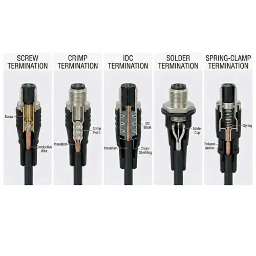
In the design of industrial interconnection systems, the termination method of M12 connectors is a critical variable that determines system robustness, installation efficiency, and long-term maintenance costs. As Industry 4.0 places increasingly stringent demands on deployment speed and signal integrity, the choices available to engineers are no longer limited to traditional screw connections or soldering.
From screw and push-in technologies suitable for flexible field wiring, to high-performance crimping designed for large-scale automated production, to insulation displacement connection (IDC) solutions engineered for 10GbE without the need for stripping, and even molded cables that offer ultimate protection—each termination method has its own irreplaceable application boundaries.
This article provides an in-depth analysis of several currently mainstream termination technologies, helping you accurately identify the interconnection solution that best aligns with Total Cost of Ownership (TCO) principles amidst complex environmental challenges and performance expectations.
1. What Are the Termination Methods for M12 Connectors
The termination method of an M12 connector refers to the physical and electrical connection between the conductor (wire or cable) and the internal contacts of the M12 connector housing. In other words, it defines how the cable “connects” to the connector, ensuring reliable signal and/or power transmission through the M12 interface in industrial environments.
In M12 connectors, the termination method determines not only the quality of the electrical connection between the connector and its internal contacts but also the stability of the mechanical connection. While the housings of different M12 connectors may appear very similar, their internal connection methods can vary significantly depending on the terminator. Consequently, engineers must select carefully.
In industrial environments with vibration, humidity, and temperature fluctuations, termination quality directly affects connection reliability, long-term stability, and equipment lifespan. Thus, selecting the appropriate termination method is one of the key factors in ensuring the long-term stable operation of the M12 interface under demanding conditions.
2. Types of M12 Connector Termination Methods
To help you more intuitively choose the right connection solution, we categorize the termination methods of M12 connectors into three core groups. These groups reflect their application stages throughout the lifecycle—including field assembly, factory prefabrication, and in-equipment integration. Moreover, this classification method applies to the entire process from design selection to final deployment, helping you achieve the optimal balance of performance, reliability, and cost across different installation environments and engineering requirements.
2.1 Field-Wireable M12 Connector Termination Methods
Field-wireable M12 connectors are designed for on-site installation. They come in handy when cable length needs adjustment during setup or when connectors must be assembled in the field for maintenance, retrofit, or expansion work.
Screw Termination M12 Connectors
Screw termination is one of the most familiar M12 connector termination methods for field wiring. You insert the stripped conductor into the contact terminal and then a screw-driven clamping mechanism secures it.
Key advantages of screw termination:
- Simple operation with minimal tooling.
- Suitable for field installation and emergency maintenance.
- Reusable and easy to service.
- Flexible for low-volume or customized applications.
Typical applications:
Sensors, actuators, machine maintenance, and field service environments.
Spring-Cage / Push-In M12 Connectors
Spring-cage (push-in) termination uses a constant-force spring mechanism to clamp the conductor automatically after insertion. This M12 termination method delivers fast wiring and strong vibration resistance. These connectors often comply with IEC 61076-2-101 and similar standards, ensuring reliable industrial performance.
Key advantages of push-in termination:
- Faster than screw termination.
- Reduces human error during installation.
- Excellent vibration resistance.
- Maintenance-free over long service life.
Typical applications:
Standardized wiring environments, industrial automation, and systems where installation speed matters.
IDC M12 Connectors
IDC, or insulation displacement connection, is a field-wireable M12 connector termination method that does not require stripping of individual conductor insulation. A precision blade pierces the insulation and makes electrical contact directly with the conductor. Note, however, that certain IDC variants require pre-stripping of the conductor insulation.
Key advantages of IDC termination:
- No stripping required (for most designs).
- Faster assembly process.
- Preserves twisted-pair geometry.
- Helps maintain signal integrity in high-speed applications.
Typical applications:
Industrial Ethernet, data transmission, and high-speed communication systems.
2.2 Factory Pre-Assembled M12 Connector Termination Methods
Manufacturers complete factory pre-assembled termination methods in a controlled environment. That gives us better repeatability, better process control, and stronger scalability for mass production.
Crimp Termination M12 Connectors
Crimp termination is a widely used M12 connector termination method in industrial cable assembly. Controlled mechanical deformation permanently joins the conductor and terminal.
Key advantages of crimp termination:
- Excellent electrical consistency.
- High reliability under vibration and long-term operation.
- Suitable for automated and semi-automated production.
- Strong balance between performance and manufacturing efficiency.
Typical applications:
Industrial Ethernet cables, automation equipment, and high-volume cable assembly.
Molded Cable Assemblies
Molded cable assemblies combine the connector and cable into a single overmolded unit. This represents one of the most robust M12 connector termination solutions for harsh environments.
Key advantages of molded cable assemblies:
- Excellent environmental protection.
- High strain relief and mechanical durability.
- Plug-and-play installation.
- Ideal for harsh industrial conditions.
While molded assemblies typically offer excellent environmental sealing, the achieved IP rating (e.g., IP67, IP68, IP69K) depends on the connector design and manufacturer specifications, not solely on the overmolding process itself.
Typical applications:
Food and beverage equipment, outdoor systems, washdown environments, and vibration-prone applications.
2.3 Device-Level M12 Connector Termination Methods
You use these termination methods when you integrate the M12 connector directly into a device, control unit, or PCB.
Solder Termination M12 Connectors
Solder termination in M12 connectors encompasses several PCB-level connection methods. These include through-hole wave soldering, surface-mount reflow soldering (SMT), and through-hole reflow (THR). Each method offers different trade-offs between mechanical strength, assembly density, and automation compatibility.
Key advantages of solder termination:
- Compact footprint.
- Suitable for high-density PCB layouts.
- Mature and widely adopted manufacturing process.
- Cost-effective for many industrial devices.
Typical applications:
Industrial control devices, sensors, and compact electronic modules.
THR M12 Connectors
THR, or through-hole reflow, combines the mechanical strength of through-hole mounting with the automation compatibility of SMT production lines.
Key advantages of THR termination:
- Compatible with automated SMT assembly.
- High mechanical strength.
- Strong vibration resistance.
- Suitable for high-reliability mass production.
Typical applications:
Modern industrial electronics, PCB-integrated connector designs, and automated manufacturing environments.
3. How to Choose the Right M12 Connector Termination Method
Choosing the right M12 connector termination method depends on the application, the environment, the production volume, and the maintenance requirements. There is no universal best choice. The right solution is the one that fits the actual engineering constraints of the project. Therefore, you should evaluate each option based on your specific needs.
- Installation Environment
For applications that require frequent on-site wiring or maintenance, such as sensors, actuators, IO-Link nodes, and mobile equipment, screw termination and push-in M12 connectors are often the better fit. On the other hand, for harsh environments involving vibration, washdown, or outdoor exposure, molded cable assemblies and crimped M12 cable solutions usually prove more reliable. They reduce the risk of loosening, moisture ingress, and contact failure.
- Production and Assembly Method
For high-volume manufacturing, crimp termination is often the most efficient M12 connector termination method. It offers short cycle times, consistent quality, and compatibility with automated crimping and testing equipment. Conversely, for low-to-medium production volumes or customized designs, screw termination and PCB solder termination give us more flexibility because they require less dedicated tooling.
- Maintenance and Serviceability
If the application requires frequent replacement, reconfiguration, or field troubleshooting, field-wireable M12 connectors with screw or push-in termination can significantly reduce maintenance time. However, when long-term reliability and fast installation matter more than repairability, molded cable assemblies and pre-assembled M12 cables make more sense. In those cases, the full assembly is usually replaced instead of repaired.
- Performance and Signal Integrity
For high-speed data transmission and industrial Ethernet applications, especially X-coded M12 connectors and other high-performance data interfaces, the termination method must support controlled impedance and strong shielding performance. Consequently, in these cases, precision crimp termination and IDC termination are often the better choices because they help preserve signal integrity and reduce installation errors.
Note: M12 Push-Pull locking variants also support these termination methods, providing tool-free mating for faster installation.
4. M12 Connector Termination and TCO
When we evaluate M12 connector termination methods, we should include more than the connector price alone in the total cost of ownership. A lower-cost termination method can create higher labor cost, more rework, longer inspection time, or greater failure risk later in the product lifecycle.
For example:
Screw termination may reduce upfront cost but increase installation time.
Crimp termination may require tooling investment but improve production efficiency.
IDC termination may reduce stripping and assembly time while supporting better signal consistency.
Molded cable assemblies may cost more initially but reduce long-term maintenance in harsh environments.
A good M12 connector selection strategy should always consider the full lifecycle cost, not just the unit price. In short, look beyond the purchase order.
5. Common M12 Connector Applications
Different M12 connector termination methods are better suited to different industrial applications.
For instance, sensors and actuators use screw termination and push-in termination widely for flexible field wiring. Meanwhile, industrial Ethernet relies on crimp termination and IDC termination for reliable signal transmission. Furthermore, food and beverage machinery often prefers molded cable assemblies for sealing and durability. In contrast, compact control devices and PCB modules use solder termination and THR termination for board-level integration. Finally, mass production systems typically employ crimp termination as the best fit for scalable cable assembly.
The following table summarizes the key termination methods, their typical applications, and characteristics:
| Termination Method | Typical Applications | Key Strengths | Key Limitations | Typical IP Rating | Production Mode |
|---|---|---|---|---|---|
| Screw | Sensors, actuators, field maintenance | Simple, reusable, minimal tooling | Slower installation, potential human error | IP67 | Low volume / field |
| Spring-Cage / Push-In | Standardized field wiring, automation | Fast, vibration-resistant, maintenance-free | Limited wire range | IP65/IP67 | Low–medium volume |
| IDC | Industrial Ethernet, high-speed data | Fast assembly, good signal integrity, no stripping (usually) | Requires precise installation, variants may need stripping | IP67 | Low volume / field |
| Crimp | High-volume cable assembly, Ethernet | Excellent consistency, reliable under vibration | Requires crimp tooling investment | IP67 | High volume |
| Molded | Harsh environments, washdown, outdoor | Superior sealing, plug-and-play, high durability | Not repairable, higher initial cost | IP67/IP68/IP69K | High volume |
| Solder (Wave/SMT) | PCB-integrated devices, compact modules | Compact, cost-effective, mature process | Difficult to repair, manual soldering variability | Depends on housing | Medium–high volume |
| THR | Automated SMT production, high-reliability PCBs | SMT compatible, strong mechanical hold | Higher design and tooling costs | IP67/IP68 | High volume |
6. Final Thoughts
Screw, push-in, crimp, IDC, solder, THR, and molded cable assemblies are all proven M12 connector termination methods used in industrial applications. In the end, the right choice depends on installation flexibility, production efficiency, maintenance strategy, environmental protection, and signal performance.
Instead of asking which M12 connector termination method is best, engineers should ask which method is most suitable for the application. In practice, screw termination gives us flexibility, crimp termination delivers consistency, and IDC termination provides fast installation with strong signal performance.
Choosing the right M12 connector termination method helps improve reliability, reduce lifecycle cost, and ensure stable performance in demanding industrial environments. As a result, your system will operate more smoothly over the long term.
7. FAQ
7.1 What is the most common M12 connector termination method?
Screw termination, push-in termination, crimp termination, and IDC are among the most common M12 connector termination methods, depending on whether the application involves field wiring, factory assembly, or industrial Ethernet. In practice, the choice varies.
7.2 Which M12 connector termination method is best for industrial Ethernet?
For industrial Ethernet, we often prefer IDC and precision crimp termination because they support signal integrity, consistent assembly, and controlled impedance.
7.3 What is the difference between screw termination and push-in termination?
Screw termination secures the conductor with a mechanical screw clamp, while push-in termination uses a spring mechanism that clamps the wire automatically after insertion. Essentially, one requires a screwdriver, the other does not.
7.4 Is IDC termination better than crimp termination?
Neither is universally better. IDC often proves faster and better for field assembly, while crimp termination usually offers greater strength for factory production and long-term repeatability.
7.5 Are molded M12 cable assemblies waterproof?
Molded M12 cable assemblies target harsh environments and typically deliver very strong sealing and strain relief, making them suitable for washdown and outdoor applications. However, you should always check the specific IP rating.
7.6 What is THR in M12 connectors?
THR stands for through-hole reflow. It combines through-hole mechanical strength with SMT-compatible automated assembly, making it suitable for PCB-mounted M12 connectors.
7. 7 How do I choose the right M12 connector termination method?
The best choice depends on installation environment, production volume, maintenance needs, vibration level, IP rating, and signal-speed requirements. Therefore, start by listing your operational constraints and then match them to the method that meets those needs.