




M8 Connector Coding Types Explained: A Complete Guide

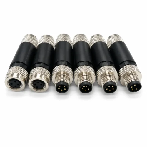
Compact connectivity means more than just small size. In sensor systems, robotics, and factory automation, engineers face increasingly dense cabling and the mixed transmission of signals, data, and power on the same machine. M8 connectors solve space issues, but their coding addresses security and interoperability. Without proper coding, connectors that look identical but carry different voltages, protocols, or signals can be accidentally connected, leading to equipment damage or network outages. Therefore, understanding M8 coding types is not optional, but a prerequisite for reliable system design.
1. What Is M8 Connector Coding?
M8 connector coding is a mechanical keying feature built into the connector’s contact carrier and mating interface. It physically prevents a connector with one coding from mating with a receptacle or plug of a different coding. This is not a subtle orientation mark; it is a deliberate geometric difference that makes incorrect connection impossible without excessive force.
M8 connector coding is standardized across two related IEC specifications. IEC 61076-2-104 defines the A-coding and B-coding types — used for screw-locking or snap-locking connectors carrying standard sensor/actuator signals and Profibus DP fieldbus. IEC 61076-2-114 defines the D-coding and P-coding types, which combine signal and power contacts for industrial Ethernet applications with data transmission up to 100 MHz. Both standards specify the shape and positioning of the insulating insert and the corresponding grooves. For engineers and installers, coding guarantees that only connectors designed for the same electrical and signal purpose can be engaged, eliminating a whole class of wiring errors at source.
2. Common M8 Connector Coding Types
该标准认可多种编码方式,但目前工业领域主要采用四种编码方式:A 编码、B 编码、D 编码以及较新的 P 编码。每种编码方式都对应一组不同的协议和功率等级。
2.1 A-Coded
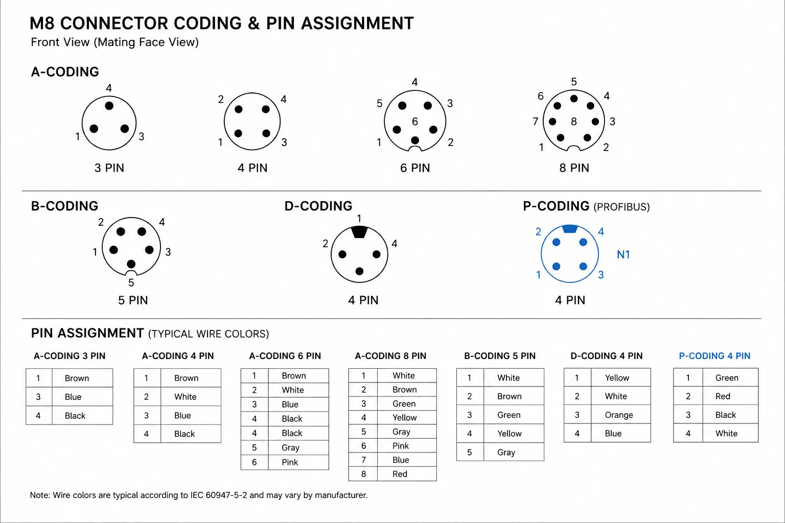
A-coded is by far the most common M8 coding. It supports pin counts of 3, 4, 6, and 8, though 3- and 4-pin versions account for the vast majority of field installations. Typical electrical ratings are 4 A per contact at 60 V AC/DC for the 3- and 4-pin variants, making them ideal for low-power signal and supply connections.
Key applications include:
- Standard sensors: proximity, photoelectric, pressure, and temperature sensors that output a simple switching or analog signal.
- IO-Link devices: This is arguably the single most important application of A-coded M8 connectors today. IO-Link uses a 3-pin or 4-pin A-coded M8 with a standardized pin assignment: Pin 1 (L+, +24 V DC), Pin 3 (L-, 0 V), Pin 4 (C/Q – combined communication and switching). A 3-pin version omits the auxiliary output, serving point-to-point IO-Link communication.
- Actuators and solenoid valves: compact pneumatic or electric actuators requiring a secure, vibration-resistant power and control interface.
Because A-coded connectors are so ubiquitous, they form the default choice for any general-purpose low-voltage signal or sensor wiring.
2.2 B-Coded
B-coded M8 connectors are designed specifically for Profibus DP fieldbus networks. They typically feature 5 pins and a keyway that prevents mixing with A-coded sensor wiring. While Profibus installations are increasingly being replaced by Ethernet-based protocols, many existing process plants and machine tool lines still rely on Profibus DP, and B-coded M8 connectors ensure backward compatibility in these brownfield environments.
Select a B-coded M8 only when your device explicitly requires Profibus DP connectivity. Do not assume it is a “safer” or “more industrial” version of A-coded; it simply serves a different bus standard.
2.3 D-Coded
D-coded M8 connectors are the compact answer to industrial Ethernet in space-constrained devices. They use 4 pins to carry Cat5e-compliant Fast Ethernet (100 Mbit/s) and are rated for 4 A at 63 V DC, with a surge voltage category of 1500 V. This rating makes D-coded M8 connectors suitable for both pure data and Power over Ethernet (PoE) applications — always confirm the exact PoE class (802.3af Type 1 or the higher-power 802.3at Type 2) against the specific connector and cable assembly datasheet, since the supported class can vary by manufacturer, wire gauge, and cable length.
Common protocols running over D-coded M8 include PROFINET, EtherCAT, and EtherNet/IP. In a robotic arm or a machine vision camera, swapping an RJ45 or even an M12 connector for a D-coded M8 saves significant space while maintaining full 100 Mbit/s bandwidth. Always choose shielded D-coded M8 connectors with 360° shield termination to ensure signal integrity in the noisy industrial environment.
2.4 P-Coded
P-coded M8 connectors are a recent addition, tailored for EtherCAT P. This protocol extends standard EtherCAT by combining 100 Mbit/s communication and power on the same four-pin M8 connector. The P-coded keying prevents accidental mating with other Ethernet variants. A single P-coded M8 cable carries two electrically isolated 24 V DC supply rails alongside real-time Ethernet data: US (system and sensor supply) and UP (peripheral supply for actuators). Each rail can deliver up to 3 A, giving a combined power budget of roughly 144 W over the same four-wire cable. This dual-rail, single-cable design enables truly compact drives and I/O modules without separate supply lines.
P-coded connectors are still specialized, but for new EtherCAT P installations in distributed servo drives or compact I/O hubs, they offer a game-changing reduction in cabling volume.
3. M8 Coding and Pin Count Reference Table
The table below summarizes the core M8 coding types as a quick selection reference.
| Coding | Typical Pin Count | Governing Standard | Primary Application | Key Electrical Parameters |
|---|---|---|---|---|
| A | 3, 4,, 6, 8 | IEC 61076-2-104 | Sensors, actuators, IO-Link, DC power | 3/4-pin: 4 A, 60 V; 6/8-pin: 1 A, 30 V |
| B | 5 | IEC 61076-2-104 | Profibus DP fieldbus | Per Profibus specification |
| D | 4 | IEC 61076-2-114 | Industrial Ethernet (PROFINET, EtherCAT, EtherNet/IP), PoE | 100 Mbit/s, 4 A, 63 V DC, 1500 V surge |
| P | 4 | IEC 61076-2-114 | EtherCAT P (data + power) | 100 Mbit/s; dual 24 V DC rails (US + UP), 3 A each, ~144 W combined |
Note: 8-pin A-coded variants are often supplier-specific and may not be covered by every edition of the standard; always verify with the manufacturer.
4. M8 Connector Coding in Key Applications
4.1 Sensors and IO-Link Nodes
For a simple inductive proximity sensor, a 3-pin A-coded M8 (L+, L-, signal) suffices. When the sensor supports IO-Link for diagnostics and parameterization, switch to a 4-pin A-coded M8 with pin 4 acting as the bidirectional C/Q line. The same A-coded socket on an IO-Link master handles both standard digital inputs and IO-Link devices, illustrating how coding alone does not define function—but it ensures you don’t plug that sensor into a D-coded Ethernet port by mistake.
4.2 Actuators and Compact Drives
Small electric grippers, valve manifolds, and stepper drives benefit from the M8’s space-saving form. For pure control signals, an A-coded connector is standard. If the actuator is part of an EtherCAT network and requires power over the same cable, a P-coded M8 delivers both motion commands and up to two independent 24 V/3 A supply rails, eliminating the need for bulky separate power connectors
4.3 Factory Automation and Distributed I/O
In a distributed I/O block, you will often find a mixture of A-coded ports for sensors and actuators, and D-coded ports for the uplink to the PLC network. Coding prevents field technicians from plugging a sensor extension into the Ethernet backbone. The physical separation of coding types thus reinforces the network hierarchy.
4.4Robotics
Robot arms and end effectors are classic tight-space environments. M8 D-coded connectors for Gigabit-capable vision sensors and A-coded connectors for gripper sensors share the same junction box without risk of mixing. The M8’s vibration-resistant thread (tightened to 0.4–0.6 Nm) maintains contact integrity even during high-speed repetitive motion.
5. How to Choose the Right M8 Coding Type
Contrary to a common misconception, coding type is not your starting point. The selection sequence should be:
- Determine the required number of pins. A simple sensor might need only 3; an IO-Link device, 4; Profibus DP, 5. Pin count is the most fundamental decision because it dictates whether a connector can even carry the needed signals.
- Identify the communication protocol or power scheme. Is it pure 24 V I/O? Then A-coded. Profibus DP? B-coded. Industrial Ethernet? D-coded. EtherCAT P with combined power? P-coded. The protocol unequivocally prescribes the coding.
- Verify electrical requirements. For D-coded, ensure 4 A and 63 V DC rating meets the PoE+ demands. For high pin-count A-coded (6 or 8), current per contact may drop to 1 A—insufficient for some loads.
- Assess the environment. For IP67, standard nickel-plated brass housings and PUR overmolded cables are fine. For washdown with chemicals, upgrade to stainless steel and IP69K. For Ethernet, always select shielded versions.
- Match mounting style and orientation. Straight or right-angled? Panel mount or cable connector? These choices affect installation depth and cable routing but are secondary to electrical and coding compatibility.
In short, pin count first, then coding, never the other way around. If a device uses 4 pins for Ethernet, D-coded is mandatory; an A-coded 4-pin will not fit, and if forced, will destroy the connector and possibly the equipment.
6. Best Practices for M8 Coded Connectors
- Respect the keying. If a connector does not slide in with minimal force, stop. Never force or modify coding.
- Torque correctly. 0.4–0.6 Nm for M8 threads. Under-torquing loses IP sealing and vibration resistance; over-torquing cracks the housing.
- Ensure shield continuity. For D- and P-coded shielded connectors, the cable shield must make a 360° bond to the connector backshell, and the connector body must be grounded to the chassis. A floating shield causes intermittent Ethernet faults.
- Dress cables properly. Use strain-relief clamps and maintain minimum bend radii, especially in moving robotic applications.
- Verify colour-coded cables. Many M8 patch cords use colour coding (e.g., blue for Ethernet, yellow for IO-Link) as a secondary visual indicator, but never rely on colour alone—coding is the final safeguard.
7. Frequently Asked Questions
7.1 What does M8 connector coding mean?
It refers to the mechanical keying built into the connector’s insulator that prevents a connector of one coding from mating with a different one, thereby eliminating wiring errors.
7.2 What is the most common M8 coding type?
A-coded, used for sensors, actuators, and IO-Link. It covers the vast majority of 24 V signal and power connections in automation.
7.3 Are all M8 connectors interchangeable?
No. Even if two connectors have the same thread size, different codings and pin counts make them physically incompatible. Always check both coding and pin count before connecting.
7.4 Do I need shielded M8 connectors for Ethernet?
Yes. For D-coded and P-coded Ethernet, always use shielded connectors with 360° termination. Unshielded versions are only suitable for low-frequency digital signals in electrically quiet environments.
7.5 Can I use an M8 connector for both data and power?
Yes. D-coded connectors can support Power over Ethernet — the exact class (802.3af Type 1 or the higher-power 802.3at Type 2) depends on the specific connector and cable datasheet — and P-coded (EtherCAT P) connectors carry two independent 24 V DC rails (US and UP), each rated up to 3 A, for a combined power budget of roughly 144 W alongside Ethernet data. A-coded can also carry power, but not Ethernet data.
7.6 When should I choose an M8 over an M12 connector?
Choose M8 when space is at a premium and the current requirement does not exceed 4 A. M12 offers higher pin counts, higher current (up to 16 A), and faster Ethernet (up to 10 Gbit/s with X-coded), but at a larger size. M8 is the optimal balance for compact signal and Fast Ethernet connections.
8. Conclusion
M8 connector coding is more than a minor mechanical detail; it is a built-in defense against miswiring that protects both equipment and production uptime. A-coded connectors dominate the world of sensors, actuators, and IO-Link. B-coded preserves compatibility with legacy Profibus networks. D-coded brings industrial Ethernet into the tightest spaces, while P-coded pushes the frontier of single-cable power and data for EtherCAT P.
By always selecting coding based on protocol and pin count, and adhering to proper torque and shielding practices, engineers can ensure that every M8 connection is safe, reliable, and future-ready. In a world where every cubic centimetre of cabinet space counts, understanding M8 coding is one of those small pieces of knowledge that yields big returns in system integrity.